Download
1 / 33
340 likes | 625 Views
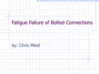
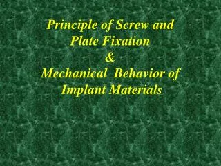
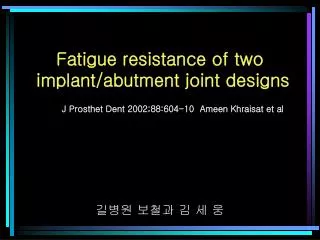
Fatigue resistance of two implant/abutment joint designs. 길병원 보철과 김 세 웅. J Prosthet Dent 2002;88:604-10 Ameen Khraisat et al. Statement of Problem. 여러 가지 mechanical failure 가 보고되어 적절한 강도를 갖는 implant system components 들이 제작되었으나 이런 제품들의 endurance 를 제대로 조사한 것은 없다 . Purpose.

E N D
Fatigue resistance of two implant/abutment joint designs 길병원 보철과 김 세 웅 J Prosthet Dent 2002;88:604-10 Ameen Khraisat et al
Statement of Problem • 여러 가지 mechanical failure가 보고되어 적절한 강도를 갖는 implant system components들이 제작되었으나 이런 제품들의 endurance를 제대로 조사한 것은 없다.
Purpose • 2 가지 single-tooth implant systems에 있어서 fatigue strength와 failure mode에 대한 joint design영향을 평가 • Brånemark / ITI • Brånemark ; hex mediated-butt joint • ITI ; 8-degree internal conical implant/abutment interface
Clinical Implications • This in vitro investigation of single-tooth implants indicated a significant difference in fatigue resistance between 2 commonly used implant systems. • Failure of the abutment screw in the Brånemark system may serve as a safety mechanism in securing the implant and the surrounding structure from bending overload.
Journal review • Osseointegrated dental implants ; A successful procedure for the treatment of complete, partial edentulism, and single-tooth replacements in both the anterior and posterior regions. • Importance of the integrity of bone/implant interface • Mechanical problems that affects single-tooth implant replacements • Screw joint instability • Loosening or fracture of the abutment or retaining screws
Journal review • Studies of the mechanical properties of implant/ abutment connections for single-tooth implant replacements. 1. Merz et al. • The tensile stresses were higher in the abutment screw threads of the butt joint design in contrast to the ITI taper connection. 2. Norton • Static bending strength 비교 • 3.75mm Brånemark implant system – hex mediated butt joint • 3.5mm Astra Tech implant system – 11 degree internal conical interface design • Brånemark implant system << Astra Tech implant system
Journal review 3. MÖllersten et al. • Static cantilever bending • Implants with a deep implant/abutment joint, such as the internal conical connection, favor resistance to bending moments in contrast to shallow one like the hex-mediated butt joint. 4. Rangert et al. • 39 fractures 0f 10,000 Brånemark implants • 3.75mm implants(different types and lengths) • No fractures of 4mm implants • 36 fractures ; Bone level was at the implant third thread or more apical. • EsthetiCone and CeraOne gold abutment screws, where the upper threads are deleted, should be introduced on the standard Brånemark system.
Journal review • 4mm implant has 30% higher fatigue resistance than a 3.75mm implants. • 향상시켜야 할 점 • The bending resistance of the abutment screw by adopting new screw geometry and material. • The implant strength by increasing the diameter 5. 107 single-tooth restorations(Brånemark) were followed (for 5 years). • 1 titanium abutment screw fractured(after 3 years) • 13 screws were replaced by gold alloy screws (between the third and fifth years) • The gold alloy screw proved higher resistance to fatigue compared with the titanium screw.
Journal review 6. Levine et al. • The internal conical implant-abutment interface (ITI system with an 8 degree tapered connection) • 3 fractures among 157 single-tooth implant restorations • All fractures • Mandibular first molar area • 3.5mm hollow implant • No fracture • 4.1mm solid screw implants
Journal review Fatigue • Is defined as the progressive crack propagation resulting in a catastrophic fracture under repeated loading below the yield stress. • The abutment screw might fracture when fatigued or overload(Versluis et al) • Fatigue was a major possible cause of implant/abutment joint instability.
Fig. 1. Assembly components of Brånemark and ITI systems. Material and methods • Used 7 assemblies of 2 implant systems • Brånemark(Mark IV; Nobel Biocare AB) • ITI(Solid screw; Institute Straumann AG, Waldenberg) 가. 25.4 mm 나. 17 mm 다. Transparent acrylic-resin blocks 1. Mounted in an engineering lathe 2. Drilling for each implant type 3. Tapping 4. The embedded depth was 7 mm to simulate 3 mm bone resorption 다 가 나
Material and methods - The diameters and lengths were those most commonly used for posterior implant replacements with the least failures.
Material and methods • Brånemark group • 7 Mark IV implants • 3 mm CeraOne abutments • Tightened to 32Ncm(electronic torque control unit) • Screw access channels ; obturated with gutta-percha plug • CeraOne abutment • Titanium abutment로 구성 • Retentive hexagon of 3.8mm length • 2mm gold alloy screw
Material and methods • ITI group • 7 solid screw implants • 4 mm solid abutments • Tightened to 35 Ncm(torque wrench) • Solid abutment • Upper cone(6 degree taper) + lower cone(8 degree taper) • The thread part of the abutment has a 2mm diameter and emerge from the abutment flat bottom.
Material and methods • Fabrication and cementation of the superstructure • Parts assembled for wax-up • Brass base (two) • Crown-forming jig • Plastic burn-out pattern • covering implant analog 2 side pins ; path controller Holed at the center with the same diameter as each implant analog
Material and methods • Fabrication and cementation of the superstructure • Crown-forming jig • One center hole of 7 mm diameter to shape a cylindrical superstructure. • 2 small side holes that passively fit the 2 pins of the corresponding base when placed together. • The analog was inserted into the hole of the base to the level of its coronal shoulder. • A separating agent(Wax separator) • The plastic burn-out pattern was placed over the implant analog. • Molten wax was flowed in the cavity around the plastic pattern. • Spruing, investing, burn-out, casting(type IV gold alloy) • Cleaned in a pickling agent(Neaacid)
Material and methods • Fabrication and cementation of the superstructure • No internal relief was provided, whereas castings with poor fit and nodules were discarded and remade. • The axial wall of each casting was milled and polished with a carbide-milling cutter and a parallel polisher. • The occlusal surface was finished with caborundum wheels and polished with silicone-points. • Zinc-phosphate cement( 3.0g/mL ratio) • Were seated with finger pressure for 10 seconds followed by a sustaining pressure of 6kg for 10 minutes. • Excess cement was removed from the margins with a plastic instrument. • Allowed to set at room temperature for an additional 50 minutes.
Material and methods • Loading machine and the loading approach • Each specimen was firmly mounted in a brass holder of a lever-type fatigue testing machine. • Serrate-type cyclic loading between 0 and 100N was applied perpendicularly to the flat surface of the underlying abutment. • The loading point was at a distance • of 11.5mm from the block surface • (lever arm length) • 100N • Generated bending moment • ; 100 x 11.5 = 1150Nmm
Material and methods • Loading machine and the loading approach • Before starting each test, a small amount of grease was used to reduce friction and wear at the loading point. • To simulate 6 years of function, a target of 1,800,000 cycles was defined. • The loading rate was 75 cycles/min that was similar to the human chewing frequency. • Every 10,000 cycles the loading machine was stopped to inspect all specimens for any deformation, decementation, and abutment loosening by a loupe(x8) and operator’s finger. • On test completion, fractured surface were examined with a SEM. • Specimen preparation and testing were performed by the same operator.
Material and methods • Statistical analysis • Fisher’s exact probability test(both-sided) was performed to determine the probability of the association of the joint design with the occurrence of fatigue failure. • Statistical significance was defined as P <.05.
Results The critical zone in the failed specimens ; at the junction between the unthreaded and thread parts of the abutment screw. Fractures were located approximately 3mm from the upper aspect of the Bråne -mark implants. No signs of decementation or abutment loosening were noticed in either implant system.
Results The coronal surface of the fractured abutment screws underwent SEM analysis. The upper area showed a different pattern from the lower one. A ; second stage(crack propagation) B ; third stage(catastrophic fracture) Vertical arrow indicates load direction
Results Upper area Lower area Lines of slender grooves perpendicular to the load direction A fine equi-axis dimple pattern
Discussion • Gold alloy abutment screw(Brånemark system) • Designed for the stabilization of the butt joint. • Allowed a higher torque application that elastically deformed the screw to work as a spring at the joint interface. • The axial preload of the screw was a determining factor for the joint stability. • Under lateral loading, tensile stresses in the abutment screw threads in the butt joint design were higher in contrast to the ITI taper connection • The butt joint opens on the tension side under lateral loading and the small screw, instead of the joint interface, is compelled to take this tension transfer.
Discussion • All failures occurred at the junction between the unthreaded (1.5mm diameter) and threaded parts(2mm diameter) of the screw. • The diameter difference caused stress concentration at the junction and resulted in fatigue crack initiation, which propagates until complete catastrophic fracture. • In a taper connection, the friction locking of the abutment to the implant with a less than 10um gap eliminated vibration and micromovement of the abutment screw. • As a result, lateral loading was resisted by the taper interface, which prevented the abutment from tilting off and protected the abutment screw from excessive stress.
Discussion • Basten et al. • CeraOne abutment의 fatigue performance를 조사 • The weak component in the implant assembly was the 4mm diameter implant, which fractured in 10 of 15 specimens. • The gold alloy abutment screw fractured in a wide range of 169,000 to 1,492,000 cycles in 4 specimens, of which 3 occurred below the screw head and 1 in the threaded part. • This study • Lateral load를 이전의 연구 보다 3 배정도 강하게 가하였으나 fatigue life가 이전의 연구보다 더 길었다. • All failures occurred at the junction between the unthreaded and threaded parts of the screw. • Neither below the screw head nor in the threaded part
Discussion • 두 연구의 차이점 • Some factors • Loading pattern • The distance between the loading and supporting points, which was about 1mm shorter in this study than in the other test. • The supporting material was acrylic resin • Has a smaller Young’s modules compared with epoxy resin used in the other test.
Discussion • Brånemark system에서 fatigue failure가 발생했을 경우 고려해야 할 점. • The implants and abutments could be brought to function by replacing the fractured abutment screws and applying technical skills to diagnose and eliminate the reasons for overload. • The fail-safe mechanism of sacrificing the abutment screw could be applied to protect the other components and the supporting tissues. • The stronger implants will not solve the problem of overload but may lead to bone damage. • For implant systems with abutment screws, the screws should be designed as the weak link because it is the most easily replaced component.
Discussion • These 2 important features contrast with those of the ITI system, where the design aims to have a strong assembly that transfers the functional load through the taper interface to the implant and secures the abutment threads. • 이번 연구의 기간은 6개월에서 5년 정도로 다양한 형태의 implant/abutment connection과 연관된 문제점들 및 장기적인 성공을 평가하고 확신하기 위해서는 좀더 긴 연구가 필요하다.
Conclusions • 이번 연구의 제한성 내에서 다음과 같은 결론을 내릴 수 있다. • For the Brånemark system • Even though the geometry and composition of the abutment screw were modified, the screw was the weak link in the implant assemblies. • The junction between the unthreaded and threaded parts of the abutment screw was the crucial point for all tested specimens in the presence of simulated bone resorption.
Conclusions • For the ITI system • The internal conical implant/abutment joint showed fatigue resistance superior to the hex mediated butt joint. • The stress dispersion over the joint interface may be the reason for the high resistance to repeated lateral loading. • For both implant system • Although the intraoral environment was not completely simulated in this study, the absence of cement failure under repeated lateral loading may add to the advantages of the use of cement-retained crowns for single tooth implant applications.
경청해 주셔서 감사합니다!!! 길병원 보철과 김 세 웅