Optimizing Detection Systems for Beam Dynamics Analysis in Experimental Physics
This document outlines various methodologies and potential locations for measuring beam properties in experimental setups. It addresses different detector schemes including solar cell arrays, Double-Sided Silicon Strip Detectors (DSSSD), and scintillating fibers, highlighting their advantages and disadvantages. The significance of understanding acceptance angles and energy resolution is emphasized, with practical configurations for slits and clamps detailed. Potential areas for implementation are suggested to enhance sensitivity and accuracy in data collection while minimizing losses.

Optimizing Detection Systems for Beam Dynamics Analysis in Experimental Physics
E N D
Presentation Transcript
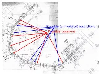
Possible (unmodeled) restrictions Possible Locations
Possible Checks • 0th order: open up and look • 1st order: • Point-parallel-point optics to image shadows • More wobbler studies to measure (a,b) acceptance • Scattering from thick foil to measure (a,b,d) acceptance
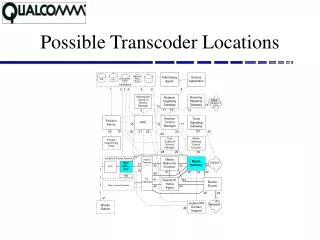
Possible Locations • Just before Q9 (maximum y envelope) • Any of the BCMs after mass slits • Interceptor position • Other ideas?
Detector schemes • Solar cell arrays • Pros: sensitive, cheap • Cons: energy, position resolution poor, • DSSSD • Pros: E,x,y position resolution OK • Cons: expensive, sensitive • Scintillating fibers • Pros: sensitive, good position resolution • Cons: complex
(x,y)=0 • (a,b)=±20mrad • dE=±4% • SLITC=25mm • SLITC=15,25mm • SLITF=45mm Substantial loss at charge slits, but none beyond that
(x,y)=0 • (a,b)=±20mrad • dE=±4% • SLITC=45mm • SLITC=45mm • SLITF=45mm No more loss at charge slits… …but additional loss points crop up
(x,y)=0 • (a,b)=±20mrad • dE=±4% • SLITC=45mm • SLITC=45mm • SLITF=45mm ED1 field clamp limits rays
(x,y)=0 • (a,b)=±20mrad • dE=±4% • SLITC=45mm • SLITC=45mm • SLITF=45mm Even if they make it past ED1, ED2 field clamp limits rays