Download
1 / 15
150 likes | 313 Views
ITRS FEP Challenges. Continued scaling will require the introduction of new materials and device structures. PIDS Logic FEOL ITRS Drivers-1. Transistor scaling to maintain historical MOSFET speed gains Historical speed metric is the MOSFET gate delay, : = CV I

E N D
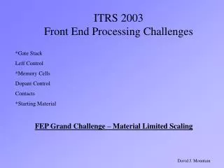
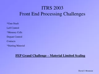
ITRS FEP Challenges Continued scaling will require the introduction of new materials and device structures
PIDS Logic FEOL ITRS Drivers-1 • Transistor scaling to maintain historical MOSFET speed gains • Historical speed metric is the MOSFET gate delay, : = CV I • MOSFET delay has historically been decreasing at a compounded annual rate of 17% per year. • The ITRS device drivers are based on the continuation of this historical rate. • A major ITRS logic challenge is that traditional scaling of bulk MOSFET devices will not permit the continuation of this trend. New device materials and structures will be required. Capacitance Power Supply Voltage MOSFET Drive Current
PIDS Logic FEOL ITRS Drivers-2 Gate + Source/Drain Capacitance of the logic gate • Limit the increase in dynamic power consumption, P • Power management requires that power supply voltage be continuously reduced. • Low voltage operation then drives the need to lower the MOSFET threshold voltage which inevitably results in increased off-state leakage. • New device structures and materials and their CMOS integration will be required to manage off-state leakage, while continuously reducing gate delay Switching Frequency P = ½ C f V2 Power supply voltage
Device Scenario Implicit in the 2003 ITRS • 2003-2007- Bulk devices with enhancements to reduce gate delay • Multiple MOSFET designs on the same chip to optimize performance and power consumption (more complex process flows) • Introduce High-k gate dielectric- enhances low voltage drive current, while reducing off-state leakage • Introduce Strained silicon channels- enhances mobility, therefore low voltage drive current • Introduce Metal gates - enhances drive current by reducing polysilicon gate depletion layer - requires two different gate materials for dual work functions • 2008-2011 Fully depleted SOI single gate devices with elevated source/drains • 2012-2018 Double- or Multiple-gate fully depleted devices e.g. FinFET
Bulk Scaling Trends/Challenges Years 2003-2007 2 metals replace dual doped poly High-k replaces Silicon Oxynitride NiSi replaces CoSi2 Strained Channel Layer ½ X every 4-6 years Lowered Drain extension Rs Lowered Metal/Silicon Contact R Gate Length Scaling and 10% 3 CD Control !!!!!
FD SOI Scaling Challenges 2008-2011 • Challenges: • Dual metal gate integration • CD Control (10% 3) • Spacer integrity • Silicide/Si contact Rc • Active Layer t control • Hi-k integration • Zero Damage Cleaning • BOX layer thickness control • Drain extension Rs and gate drain overlap • Epi-Bulk interface contamination Dual metal gates (nMOS, pMOS) Contact NiSi Sidewall spacer High-k Dielectric Epi Elevated Contact Box Layer Strained Silicon Active Layer Active layer thickness ~0.4 Lgate, must scale with gate length
Multiple Gate Device Scaling 2011-2018 Silicon Fin Channel Metal Gates 1 & 2 1 2 Source Drain Buried Oxide Layer = High N doping = Light P doping
Multi-Gate FET Scaling Challenges • Challenges: • Gate CD Control • Metal Gate Integration • Fin Thickness control • Drain Extension parasitic resistance • Silicon/Silicide contact Resistance • Sidewall spacer integrity • High-k gate dielectric integration • Zero damage cleaning Drain Extensions Gate 1 Drain Source Gate 2 Sidewall Spacers Hi-k Gate Dielectric Layers Fin Thickness ~0.8 Lgate, must scale with gate length scaling
Starting Materials Challenges • Introduction and evolution of new substrate materials • Strained Silicon • Silicon on Insulator for Fully Depleted devices • Continuous defect recognition and reduction • Introduction of Next Generation (~450mm) wafer size • ITRS sets requirement for year 2011 introduction • Industry R&D is not in place to meet this timing • Traditional manufacturing methods may not be economically scaleable
DRAM Capacitor Scaling Challenges • A minimum (25-35 fF) storage capacitance is required to maintain bit integrity • Storage capacitor size must continuously decrease • DRAM bit capacity increases 2x every 2 years • DRAM chip size remains constant • Traditional capacitor materials can no longer satisfy scaling requirements • Polysilicon will be replaced by metal for capacitor plates • Silicon oxynitride will be replaced by new dielectric materials having higher dielectric constant
Technology Migration of Stack Capacitor 100nm 70nm 45 nm 25 nm MIS MIM MIM MIM Metal Ta2O5, Al2O3 SrRuO3 ? epi-BST ? New Hi-K Metal Oxynitride Poly Si
DRAM Trench Capacitor Scaling 45nm node 57:1 Trench
128M 32M 64M 16M Flash Memory Scaling Challenges • Inter-Poly dielectric thickness must be reduced to maintain coupling ratio in order to compensate for reduction in floating gate area • Tunnel dielectric must be scaled in a way to ensure charge retention • New, high k dielectric materials are needed for continued scaling of the inter-poly dielectric • New dielectric structures are needed for thickness reduction of tunnel dielectric
Major 2005 Initiatives • Address Wafer Size Progression - Fundamental Technical and Economic Issues Associated with Large Diameter Wafers (Crystal Growth and Manufacturing Equipment) Need to be Better Identified and Quantified - Development of Solutions is Already Behind Schedule • Work with Design / Litho / PIDS to Resolve Gate CD Control Tolerances • Consider Overlapping Alternate Scenarios (Bulk, FD SOI, FINFET) - FEP Recommendation is to Extend Bulk Devices (using parallel lines) - In cases where likely scenario is not clear (FD SOI vs FINFET), consider parallel lines (industry survey to be considered) • Work with PIDS on Key Device Parameters -Validate Models for Poly-Depletion - Develop Model-Based Doping Requirements for Non-Bulk Devices -Re-Evaluate Gate Leakage Requirements • Address Wafer Edge Exclusion - New Processes, e.g. FD SOI, Immersion Lithography Make it Exceedingly Difficult to Maintain Status Quo, Yet Need is to Reduce Exclusion - FEP and YE to Provide Inputs to Factory Integration to Help Ensure that We Don’t Immediately Hit Red Wall
Major 2005 Initiatives- Memory • Review Flash Memory • Timing of nodes • Clarify definition of NOR minimum feature size • Evaluate a factor and chip size • Evaluate dielectric scaling requirements • Add potential solutions • Generate requirements for embedded flash • Review and Revise DRAM Sections - Generate requirements for embedded DRAM - Reevaluate a factor and chip size - Reevaluate storage capacitor requirements and materials • Include Alternative Memory Devices - SONOS, PCM, Floating Body