Download
1 / 55
560 likes | 610 Views
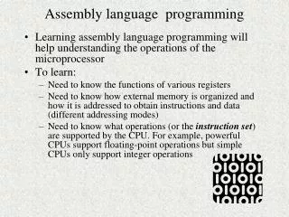
Learn the basics of Assembly Language Programming of 8085 microprocessor through an in-depth presentation. Topics include programming model, instruction set, addressing modes, and example programs. Understand the differences between machine language and assembly language.

E N D
Assembly Language Programming of 8085 Presentation By: Shehrevar Davierwala Contact : shehrevar@live.com Lecturer at GES’S Katgara Polytechnic Institute
Topics • Introduction • Programming model of 8085 • Instruction set of 8085 • Example Programs • Addressing modes of 8085 • Instruction & Data Formats of 8085
1. Introduction • A microprocessor executes instructions given by the user • Instructions should be in a language known to the microprocessor • Microprocessor understands the language of 0’s and 1’s only • This language is called Machine Language
For e.g. 01001111 • Is a valid machine language instruction of 8085 • It copies the contents of one of the internal registers of 8085 to another
A Machine language program to add two numbers 00111110 ;Copy value 2H in register A 00000010 00000110 ;Copy value 4H in register B 00000100 10000000 ;A = A + B
Assembly Language of 8085 • It uses English like words to convey the action/meaning called as MNEMONICS • For e.g. • MOV to indicate data transfer • ADD to add two values • SUB to subtract two values
Assembly language program to add two numbers MVIA, 2H ;Copy value 2H in register A MVIB, 4H ;Copy value 4H in register B ADDB ;A = A + B Note: • Assembly language is specific to a given processor • For e.g. assembly language of 8085 is different than that of Motorola 6800 microprocessor
Microprocessor understands Machine Language only! • Microprocessor cannot understand a program written in Assembly language • A program known as Assembler is used to convert a Assembly language program to machine language Assembly Language Program Assembler Program Machine Language Code
Low-level/High-level languages • Machine language and Assembly language are both • Microprocessor specific (Machine dependent) so they are called • Low-level languages • Machine independent languages are called • High-level languages • For e.g. BASIC, PASCAL,C++,C,JAVA, etc. • A software called Compiler is required to convert a high-level language program to machine code
Accumulator Register Array ALU Memory Pointer Registers Flags Instruction Decoder Timing and Control Unit 2. Programming model of 8085 16-bit Address Bus 8-bit Data Bus Control Bus
8- Lines Bidirectional 16- Lines Unidirectional
Overview: 8085 Programming model • Six general-purpose Registers • Accumulator Register • Flag Register • Program Counter Register • Stack Pointer Register
Six general-purpose registers • B, C, D, E, H, L • Can be combined as register pairs to perform 16-bit operations (BC, DE, HL) • Accumulator – identified by name A • This register is a part of ALU • 8-bit data storage • Performs arithmetic and logical operations • Result of an operation is stored in accumulator
Flag Register • This is also a part of ALU • 8085 has five flags named • Zero flag (Z) • Carry flag (CY) • Sign flag (S) • Parity flag (P) • Auxiliary Carry flag (AC)
These flags are five flip-flops in flag register • Execution of an arithmetic/logic operation can set or reset these flags • Condition of flags (set or reset) can be tested through software instructions • 8085 uses these flags in decision-making process
Program Counter (PC) • A 16-bit memory pointer register • Used to sequence execution of program instructions • Stores address of a memory location • where next instruction byte is to be fetched by the 8085 • when 8085 gets busy to fetch current instruction from memory • PC is incremented by one • PC is now pointing to the address of next instruction
Stack Pointer Register • a 16-bit memory pointer register • Points to a location in Stack memory • Beginning of the stack is defined by loading a 16-bit address in stack pointer register
3.Instruction Set of 8085 • Consists of • 74 operation codes, e.g. MOV • 246 Instructions, e.g. MOVA,B • 8085 instructions can be classified as • Data Transfer (Copy) • Arithmetic • Logical and Bit manipulation • Branch • Machine Control
1. Data Transfer (Copy) Operations • Load a 8-bit number in a Register • Copy from Register to Register • Copy between Register and Memory • Copy between Input/Output Port and Accumulator • Load a 16-bit number in a Register pair • Copy between Register pair and Stack memory
Example Data Transfer (Copy) Operations / Instructions • Load a 8-bit number 4F in register B • Copy from Register B to Register A • Load a 16-bit number 2050 in Register pair HL • Copy from Register B to Memory Address 2050 • Copy between Input/Output Port and Accumulator MVIB, 4FH MOVA,B LXIH, 2050H MOVM,B OUT 01H IN 07H
2. Arithmetic Operations • Addition of two 8-bit numbers • Subtraction of two 8-bit numbers • Increment/ Decrement a 8-bit number
Example Arithmetic Operations / Instructions • Add a 8-bit number 32H to Accumulator • Add contents of Register B to Accumulator • Subtract a 8-bit number 32H from Accumulator • Subtract contents of Register C from Accumulator • Increment the contents of Register D by 1 • Decrement the contents of Register E by 1 ADI 32H ADDB SUI 32H SUB C INR D DCR E
3. Logical & Bit Manipulation Operations • AND two 8-bit numbers • OR two 8-bit numbers • Exclusive-OR two 8-bit numbers • Compare two 8-bit numbers • Complement • Rotate Left/Right Accumulator bits
Example Logical & Bit Manipulation Operations / Instructions • Logically AND Register H with Accumulator • Logically OR Register L with Accumulator • Logically XOR Register B with Accumulator • Compare contents of Register C with Accumulator • ComplementAccumulator • RotateAccumulator Left ANAH ORAL XRA B CMP C CMA RAL
4. Branching Operations These operations are used to control the flow of program execution • Jumps • Conditional jumps • Unconditional jumps • Call & Return • Conditional Call & Return • Unconditional Call & Return
Example Branching Operations / Instructions • Jump to a 16-bit Address 2080H if Carry flag is SET • Unconditional Jump • Call a subroutine with its 16-bit Address • Return back from the Call • Call a subroutine with its 16-bit Address if Carry flag is RESET • Return if Zero flag is SET JC 2080H JMP 2050H CALL 3050H RET CNC 3050H RZ
5. Machine Control Instructions These instructions affect the operation of the processor. For e.g. HLT Stop program execution NOP Do not perform any operation
4. Writing a Assembly Language Program • Steps to write a program • Analyze the problem • Develop program Logic • Write an Algorithm • Make a Flowchart • Write program Instructions using Assembly language of 8085
Program 8085 in Assembly language to add two 8-bit numbers and store 8-bit result in register C. • Analyze the problem • Addition of two 8-bit numbers to be done • Program Logic • Add two numbers • Store result in register C • Example 10011001 (99H) A +00111001 (39H) D 11010010 (D2H) C
Translation to 8085 operations 3. Algorithm • Get two numbers • Add them • Store result • Stop • Load 1st no. in register D • Load 2nd no. in register E • Copy register D to A • Add register E to A • Copy A to register C • Stop processing
4. Make a Flowchart Start • Load 1st no. in register D • Load 2nd no. in register E Load Registers D, E Copy D to A • Copy register D to A • Add register E to A Add A and E • Copy A to register C Copy A to C • Stop processing Stop
5. Assembly Language Program • Get two numbers • Add them • Store result • Stop • Load 1st no. in register D • Load 2nd no. in register E MVI D, 2H MVI E, 3H • Copy register D to A • Add register E to A MOV A, D ADD E • Copy A to register C MOV C, A • Stop processing HLT
Program 8085 in Assembly language to add two 8-bit numbers. Result can be more than 8-bits. • Analyze the problem • Result of addition of two 8-bit numbers can be 9-bit • Example 10011001 (99H) A +10011001 (99H) B 100110010 (132H) • The 9th bit in the result is called CARRY bit.
How 8085 does it? • Adds register A and B • Stores 8-bit result in A • SETS carry flag (CY) to indicate carry bit 10011001 99H A + 10011001 B 99H 0 1 10011001 00110010 99H 32H A CY
A CY • Storing result in Register memory 1 10011001 32H Register B Register C • Step-1 Copy A to C • Step-2 • Clear register B • Increment B by 1
2.Program Logic • Add two numbers • Copy 8-bit result in A to C • If CARRY is generated • Handle it • Result is in register pair BC
Translation to 8085 operations 3. Algorithm • Load two numbers in registers D, E • Add them • Store 8 bit result in C • Check CARRY flag • If CARRY flag is SET • Store CARRY in register B • Stop • Load registers D, E • Copy register D to A • Add register E to A • Copy A to register C • Copy A to register C • Use Conditional Jump instructions • Clear register B • Increment B • Stop processing
4. Make a Flowchart Start If CARRY NOT SET False Load Registers D, E Clear B Copy D to A Increment B True Add A and E Copy A to C Stop
5. Assembly Language Program • Load registers D, E MVI D, 2H MVI E, 3H • Copy register D to A • Add register E to A MOV A, D ADD E • Copy A to register C • Copy A to register C MOV C, A • Use Conditional Jump instructions JNC END MVI B, 0H INR B • Clear register B • Increment B • Stop processing HLT END:
4. Addressing Modes of 8085 • Format of a typical Assembly language instruction is given below- [Label:] Mnemonic [Operands] [;comments] HLT MVI A,20H MOVM,A ;Copy A to memory location whose address is stored in register pair HL LOAD:LDA2050H ;Load A with contents of memory location with address 2050H READ:IN07H ;Read data from Input port with address 07H
The various formats of specifying operands are called addressing modes • Addressing modes of 8085 • Register Addressing • Immediate Addressing • Memory Addressing • Input/Output Addressing
1. Register Addressing • Operands are one of the internal registers of 8085 • Examples- MOVA, B ADDC
2. Immediate Addressing • Value of the operand is given in the instruction itself • Example- MVIA, 20H LXIH, 2050H ADI 30H SUI 10H
3. Memory Addressing • One of the operands is a memory location • Depending on how address of memory location is specified, memory addressing is of two types • Direct addressing • Indirect addressing
3(a) Direct Addressing • 16-bit Address of the memory location is specified in the instruction directly • Examples- LDA2050H ;load A with contents of memory location with address 2050H STA3050H ;store A with contents of memory location with address 3050H
3(b) Indirect Addressing • A memory pointer register is used to store the address of the memory location • Example- MOVM, A;copy register A to memory location whose address is stored in register pair HL H L A 30H 20H 50H 30H 2050H
4. Input/Output Addressing • 8-bit address of the port is directly specified in the instruction • Examples- IN 07H OUT 21H
5. Instruction & Data Formats 8085 Instruction set can be classified according to size (in bytes) as • 1-byte Instructions • 2-byte Instructions • 3-byte Instructions
1. One-byte Instructions • Includes Opcode and Operand in the same byte • Examples-
1. Two-byte Instructions • First byte specifies Operation Code • Second byte specifies Operand • Examples-