Download
1 / 14
170 likes | 450 Views
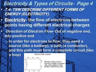
The Control of Electricity in Circuits. Electricity vs. Static Electricity. 1a ) What’s the difference between current electricity and static electricity? Current electricity is the flow of electrons in a circuit through a conductor

E N D
Electricity vs. Static Electricity • 1a) What’s the difference between current electricity and static electricity? • Current electricity is the flow of electrons in a circuit through a conductor • Static electricity is the electric charge that builds up on the surface of an object. Static electricity discharges when it is given a path, but it does not continue to flow
AC vs DC • 1b) What do AC and DC stand for and what’s the difference between them? • Alternating current (AC) flows back and forth at regular intervals called cycles. • Direct current (DC) only flows in one direction
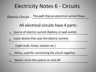
Current Electricity • 2. a) Define Current electricity? • Current electricity is the continuous flow of electrons in a circuit • 2 conditions must be met for electrons to flow continuously: • (1) The flow of electrons requires an energy source • (2) The electrons will not flow unless they have a complete path to follow • What is an electricalcircuit • An electric circuit includes an energy source, a conductor and a load
Electric Circuits See figure 11.4 on p.434
Electric Circuits • 4a) electrical load • converts the electrical energy to another form of energy • 4b) switch • A device that turns the circuit on/off by closing or opening the circuit • When the switch is closed • the circuit is complete and electrons (-) can flow • An open switch means there is a • break in the path so the electrons cannot flow through the circuit • The circuit is turned OFF when the switch is open.
Circuit Diagrams • 5a) What is a circuit diagram? • Diagram with special symbols thatshow the components andconnections in a circuit • 5b) Why are they useful? • Makes it easier to plan and analyze a circuit before you build it. • 5c) List the 2 rules to follow when drawing circuit diagrams: • Always use a ruler to draw straight lines for the conducting wires • Makes right angle corners so that your finished diagram is a rectangle
Series and Parallel Circuits • 7a) What is a series circuit? • A series circuit has components that are arranged one after another in series. • 7b) How many paths does a series circuit have to allow the flow of electrons? • one • 8a) What is a parallel circuit? • A parallel circuit has parts that are arranged so that the electrons can flow along more than one path
Electrical Safety • List, define and explain how 3 common safety devices work.
Electrical Safety • List, define and explain how 3 common safety devices work.
Electrical Safety • List, define and explain how 3 common safety devices work.
Electrical Safety • List, define and explain how 3 common safety devices work.