Download
1 / 33
330 likes | 358 Views
Learn to calculate potential changes, EMF, voltage, resistance, power dissipation in circuits. Understand Kirchhoff's loop rule, Ohm's law, and work on problems.

E N D
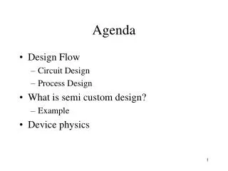
Today’s agenda: Potential Changes Around a Circuit. You must be able to calculate potential changes around a closed loop. Electromotive force (EMF), Terminal Voltage, and Internal Resistance. You must be able to incorporate all of the above quantities in your circuit calculations. Electric Power. You must be able to calculate the electric power dissipated in circuit components. Examples.
Kirchhoff’s loop rule Recall (lecture 7): voltage drops across circuit components connected in series add Vab C1 C2 C3 Vab = V1 + V2 + V3 a b V2 V3 V1 Generalization: Loop rule • around any closed loop: • reflects energy conservation (around any closed path, Uf=Ui) strictly:
Recipe for Kirchhoff’s loop rule • Assign (guess) direction of current I • positive I: current flows in this direction • negative I: current flows in opposite direction 5 10 2. Pick travel direction (clockwise or counterclockwise) I a - + 9 V 3. Add up voltage differences Vi , set sum to zero sign rules: battery voltage counts positive if you travel from – to + resistor voltage counts negative of you travel with current start at point a: +9V – I 5 - I 10 =0 I=9V / 15 = 0.6A Ohm’s law V=I R
Example: Loop rule in circuit of 3 resistors and 2 batteries R1 R2 R3 a b V1 V2 V3 - + - + I VB VA • Assign current direction 2. Pick travel direction: clockwise 3. Add voltages - V1- V2- V3 + VA - VB = 0 - V1 - V2- V3+ VA - VB = 0 - V1 - V2 - V3+ VA - VB = 0 - V1 - V2 - V3 + VA- VB= 0 - V1 - V2 - V3 + VA - VB= 0 - V1 - V2 - V3 + VA - VB = 0 - V1- V2 - V3 + VA - VB = 0 - IR1 - IR2 - IR3 + VA - VB = 0 Recommendation: choose your path around the circuit in the same direction as your guessed current.
Example:calculate I, Vab,and Vba for the circuit shown. To be worked at the blackboard in lecture. 5 b 10 - + a I 9 V +9 – 5 I – 10 I = 0 +9– 5 I – 10 I = 0 +9 – 5 I– 10 I = 0 +9 – 5 I – 10 I = 0 +9 – 5 I – 10 I = 0 15 I = +9 I = +9/15 = 0.6 A
Example: calculate I, Vab,and Vba for the circuit shown. 5 b b 10 - + a a I = 0.6 A 9 V Va+ 9 – 5 (0.6) = Vb Va+ 9– 5 (0.6) = Vb Va + 9 – 5 (0.6)= Vb Va + 9 – 5 (0.6) = Vb Va + 9 – 5 (0.6) = Vb Vab = Va – Vb = – 9 + 5 (0.6) = -6 V
Example: calculate I, Vab,and Vba for the circuit shown. 5 b b 10 - + a a I = 0.6 A 9 V Vb– 10 (0.6) = Va Vb – 10 (0.6) = Va Vb – 10 (0.6) = Va Vb – 10 (0.6) = Va Vba = Vb – Va = + 10 (0.6) = +6 V
Example: calculate I, Vab,and Vba for the circuit shown. 5 b 10 - + a I = 0.6 A 9 V Note: Vba = +6 V = - Vab , as expected
Example: calculate I, Vab,and Vba for the circuit shown. Graph the potential rises and drops in this circuit. 5 b 10 - + a I = 0.6 A 9 V 5 I = 3V b = 9V 10 I = 6V a
Example:calculate I, Vab,and Vba for the circuit shown. To be worked at the blackboard in lecture. 5 b 10 - - + + a I 9 V 6 V + 9 – 6 – 5 I – 10 I =0 + 9 – 6 – 5 I – 10 I = 0 + 9 – 6 – 5 I– 10 I = 0 + 9 – 6 – 5 I – 10 I= 0 + 9 – 6 – 5 I – 10 I = 0 + 9 – 6 – 5 I – 10 I = 0 15 I = 3 I = 0.2 A
Example: calculate I, Vab,and Vba for the circuit shown. 5 b 10 - - + + a I = 0.2 A 9 V 6 V Va+ 9 – 6 – 5 (0.2) = Vb Va+ 9 – 6 – 5 (0.2) = Vb Va + 9 – 6– 5 (0.2) = Vb Va + 9– 6 – 5 (0.2) = Vb Va + 9– 6 – 5 (0.2) = Vb Va + 9– 6 – 5 (0.2) = Vb Vab = Va – Vb = – 9+ 6 + 5 (0.2) = – 2 V
Example: calculate I, Vab,and Vba for the circuit shown. The smart way: Vba = - Vab = +2 V 5 b 10 - - + + a I = 0.2 A 9 V 6 V Vb – 10 (0.2) = Va Vb– 10 (0.2) = Va Vb– 10 (0.2) = Va Vb – 10 (0.2) = Va Vba = Vb – Va = + 10 (0.2) = + 2 V
Example: calculate I, Vab,and Vba for the circuit shown. What if you guess the wrong current direction? 5 b 10 - - + + a I 9 V 6 V – 10 I – 5 I +6 – 9 = 0 – 10 I – 5 I+6 – 9 = 0 – 10 I – 5 I +6– 9 = 0 – 10 I – 5 I +6 – 9 = 0 – 10 I – 5 I +6 – 9 = 0 – 10 I – 5 I +6 – 9 = 0 15 I = – 3 I = – 0.2 A oops, guessed wrong direction, no big deal!
DC Currents • in Physics 2135, (almost) all currents are “direct current.” • d.c. currents flow in one direction, from + to -. • we will not encounter ac (alternating currents) much • analysis of ac current is more complex • household current is ac, assuming dc will be “close enough” to give you “a feel” for the physics.
Today’s agenda: Potential Changes Around a Circuit. You must be able to calculate potential changes around a closed loop. Electromotive force (Emf), Terminal Voltage, and Internal Resistance. You must be able to incorporate all of the above quantities in your circuit calculations. Electric Power. You must be able to calculate the electric power dissipated in circuit components, and incorporate electric power in work-energy problems. Examples.
Ideal versus real voltage sources • ideal battery (or other voltage source): • voltage does not depend on the current flowing • real battery: voltage does depend on current, • typically voltage decreases with increasing current (load) How to model a real battery? • real battery consists of ideal battery + internal resistance Voltage of ideal battery is called electromotive force (emf) - + r a b internal resistance r
EMF and terminal voltage The electromotive force (emf) of a voltage source is the potential difference it produces when no current is flowing. emf is not a force! Can the emf be measured? • hook up a voltmeter: (emf) - • as soon as you connect the voltmeter, current flows + a b • you can only measure terminal voltage Vab, but not emf I An ideal voltmeter would be able to measure . The “battery” is everything inside the green box.
- + r To model a battery, simply include an extra resistor to represent the internal resistance, and label the voltage source* as an emf instead of V (units are still volts): a b If the internal resistance is negligible, simply don’t include it! If you are asked to calculate the terminal voltage, it is just Vab = Va – Vb, calculated using the techniques I am showing you today. (Terminal voltage is usually expressed as a positive number, so it is better to take the absolute value of Vab.) *Remember, all sources of emf—not just batteries—have an internal resistance.
Example: a battery is known to have an emf of 9 volts. If a 1 ohm resistor is connected to the battery, the terminal voltage is measured to be 3 volts. What is the internal resistance of the battery? R=1 Loop rule: I emf - + a b terminal voltage r terminal voltage Vab
R=1 I emf - + a b A rather unrealistically large value for the internal resistance of a 9V battery.
Today’s agenda: Potential Changes Around a Circuit. You must be able to calculate potential changes around a closed loop. Emf, Terminal Voltage, and Internal Resistance. You must be able to incorporate all of the above quantities in your circuit calculations. Electric Power. You must be able to calculate the electric power dissipated in circuit components, and incorporate electric power in work-energy problems. Examples.
Electric Power • power in terms of work done by a force: • work done by electric force moving charge q through potential difference V • for infinitesimal charge dq • instantaneous power:
P<0 means loss of electric energy • P>0 means gain of electric energy • For resistors: using Ohm’s “law” V=IR, we can write P = I2R = V2/R.
Example: an electric heater draws 15.0 A on a 120 V line. How much power does it use and how much does it cost per 30 day month if it operates 3.0 h per day and the electric company charges 10.5 cents per kWh. For simplicity assume dc current. Household current is ac rather than dc. Our calculation will be a reasonable approximation to reality.
An electric heater draws 15.0 A on a 120 V line. How much power does it use. How much does it cost per 30 day month if it operates 3.0 h per day and the electric company charges 10.5 cents per kWh.
How much energy is a kilowatt hour (kWh)? So a kWh is a “funny” unit of energy. K (kilo) and h (hours) are lowercase, and W (James Watt) is uppercase.
Example: A 12 V battery with 2 internal resistance is connected to a 4 resistor. Calculate (a) the rate at which chemical energy is converted to electrical energy in the battery, (b) the power dissipated internally in the battery, and (c) the power output of the battery. R=4 - + = 12 V I r=2
Calculate (a) the rate at which chemical energy is converted to electrical energy in the battery. R=4 I - + = 12 V r=2 Start at negative terminal of battery… - I R2 - I R4 = 0 I = / (R2 + R4) =12 V / 6 = 2 A Energy is converted at the rate Pconverted=I=(2 A)(12 V)=24W.
Calculate (b) the power dissipated internally in the battery. R=4 - + = 12 V r=2 I=2A Pdissipated = I2r = (2 A)2 (2 ) = 8 W. Calculate (c) the power output of the battery. Poutput = Pconverted - Pdissipated = 24 W - 8 W = 16W.
Calculate (c) the power output of the battery (double-check). R=4 - + = 12 V r=2 I=2A The output power is delivered to (and dissipated by) the resistor: Poutput = Presistor = I2 R = (2 A)2 (4 ) = 16W.
Example: a 3 volt and 6 volt battery are connected in series, along with a 6 ohm resistor. The batteries* are connected the “wrong” way (+ to + or - to -). What is the power dissipated in the resistor? In the 3 volt battery? 6 - - + + a I 6 V 3 V Starting at point a... + 6 – 3 – 6 I = 0 I = (6 – 3) / 6 = 0.5 A *Assume zero internal resistance unless the problem suggests otherwise.
What is the power dissipated in the resistor? 6 - - + + a PR = I2R = (0.5)2 (6) = 1.5 W I = 0.5 A 6 V 3 V What is the power dissipated in the 3 volt battery? P3V = IV = (0.5) (3) = 1.5 W P6V = IV = (0.5) (6) = 3 W = PR + P3V Note: