Download
1 / 26
280 likes | 589 Views
DC Circuits Lab. Professor Ahmadi ECE 002. Objectives. Constructing a Series Circuit Ohm’s Law Review Breadboard Overview DC Power Supply Review Measuring the D.C. Voltage in the Series Circuit Multimeter Overview. Today we will build this series circuit. Determine the current

E N D
DC Circuits Lab Professor Ahmadi ECE 002
Objectives • Constructing a Series Circuit • Ohm’s Law Review • Breadboard Overview • DC Power Supply Review • Measuring the D.C. Voltage in the Series Circuit • Multimeter Overview
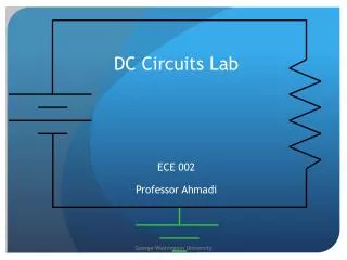
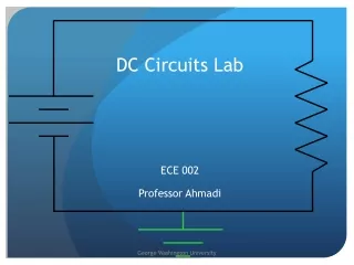
Today we will build this series circuit Determine the current Use Ohm’s Law: V = I x R 3V = Ix 1000 Ω Solve for I: I=3V / 1000 Ω = 3milliAmps I = ? Amps 3V • Series Circuit From Lecture R = 1KΩ 0V
How to Build the Circuit A 1K Ohm Resistor (Ask your GTA for these materials) Breadboard DC Voltage Source 2 sets of Banana Clip to mini-grabber wires I = 3mA 3V • We need 5 components R = 1KΩ 0V
The Breadboard • The breadboard is building circuits quickly without the need for soldering • You can plug resistors and wires right into the board
The Breadboard • The 5 holes in each row are wired together underneath the breadboard • The rows themselves are not wired together • The rows do not connect over the bridge • The columns between the blue and red bars are connected vertically • We typically use these as ‘power rails’ • The left side we use for positive voltage • The right side we use for negative voltage BRIDGE
Setting up the breadboard • Plug 1 end of the 1K resistor in the top row, on the left side of the bridge • Plug the other end of the resistor into the top row, on the right side of the bridge
Setting Up the DC Power Supply This DC Power supply is capable of generating voltages from -25V to 25V. For this lab, we will be using the 6V supply terminals. First, press the Power Button to turn it on. George Washington University
Setting Up the DC Power Supply Press Output On/Off once to turn on the output. Press the +6V button to tell the power supply that we want to alter the output from the 6V terminals. Once done, your screen should look the same as it does on this slide. George Washington University
Setting Up the DC Power Supply Press this arrow to Select the desired digit This is the digit we want to adjust Rotate this dial to alter the output value. Use the dial to increase the display value to 3 volts as shown. Note: You can safely ignore the value of the right most digit for this experiment. Once you have reached 3V, Press Output On/Off once to turn the output OFF while you hook up the circuit. George Washington University
Connecting the Power Supply to your Circuit Plug the ‘banana’ end of your cables into the 6V terminals of your power supply Connect the mini-grabber ends of the cables around your 1K resistor on the breadboard After attaching the mini-grabbers to your circuit, press the Output On/Off to apply 3 Volts across your 1K resistor George Washington University
Measuring the Voltage Across the Resistor…Using the Multimeter
What is a Multimeter? • A tool capable of measuring a variety of different quantities. • Possible Measurements • Current (Amperes) • Resistance (Ohms) • Voltage (Volts)
How is the Multimeter different than the Oscilloscope? Oscilloscope • Numerical Output Displayed • Represents a complete signal with a single value. • Measures voltage, current and resistance. • Graphical Output Displayed • Shows how a signal changes over time • Many only display voltage Multimeter
Explanation of Controls Setting up the multimeter for various measurements.
Taking measurements with the Multimeter First, we connect our wires. • One wire is always connected to the black terminal. This is called the common terminal. • The red terminal is used when measuring voltage, resistance and small currents. • The white terminal is used when measuring large currents. TO DO: Using another set of banana to mini-grabber cables, connect the banana end to the red & black terminals
Taking measurements with the Multimeter • Next, we turn it on and select the item to measure. • Choose from: • Current • Resistance • Voltage TO DO: Since we want to measure the voltage across our 1K ohm resistor, press the Voltage button Power Button
Taking measurements with the Multimeter • Now, we select our scale. • Either select a scale appropriate for your measurement or choose AUTO and let the multimeter select the appropriate scale for you. • Measuring the voltage from across the 1K resistor (~3V), you wouldn’t want to choose 200mV (much too small) or 200V (much too large). Instead, the 2V selection is more suitable.
Taking measurements with the Multimeter • While your circuit is attached to the power supply… • Attach the minigrabber end around the 1K resistor • Press the “POWER” button on the multimeter and take a reading!!
Building & Verifying Series Circuit #2 3V • Resistors connected by only 1 terminal, back-to-back, are considered to be in ‘series’ R1 = 1KΩ • Ohm’s Law States: V(R1) = 1.5mA x 1K Ω = 1.5V V(R2) = 1.5mA x 1K Ω = 1.5V R2 = 1KΩ • We are now going to build the circuit, and verify the voltage drops… 0V
Setting up the breadboard • Turn off the 3V supply and disconnect the cables • Disconnect the cables to the minigrabbers to the multimeter • Obtain a 2nd 1K resistor • Plug one end of the resistor into a hole in the same row as the end of the other resistor • Plug the other end into a hole in another row
Taking measurements with the Multimeter • Set the Power Supply to 3V • Attach the power supply leads as follows • Measure the voltage across each resistor with the multimeter
Resistors in Parallel 3V • Resistors connected at 2 terminals, sharing the same node on each side, are considered to be in ‘parallel’ • The voltage is the same on both branches of the circuit • The current will split! • It is now up to you to build this circuit and verify the voltages R1 = 1KΩ R2 = 1KΩ 0V
Including a Diode In the Circuit 3V • We’ll use LEDs (Light Emitting Diodes) for our circuits. • Unlike resisters, the two diode leads (wires) must be connected in the correct way. • The longer lead (anode) should be connect so that current flows through it and to the shorter lead (cathode). R1 = 1KΩ 0V • Note: In some diodes, a stripe is used to indicate the cathode lead. Round diodes often have a flat side, indicating the cathode.
Your Turn 1) Build the parallel circuit (in the last slide) and measure the voltage across it Using Ohm’s Law, what is the current through each resistor? What is the total current in the circuit? Show your TA your circuit, measurements, and calculations 2) In your parallel circuit, change one of the 1K resistors to a 2K resistor Measure the voltage across each resistor Use Ohm’s law to determine the current through each resistor Show your TA… 3) Rebuild the two resistor series circuit… Change one of the 1K resistors to a 2K resistor Measure the voltage across each resistor Use Ohm’s law to determine the current through each resistor Show your TA…
Your Turn 4) Build a circuit with a diode in series with a 1K resistor Using Ohm’s Law, what is the current through the resistor? What is the total current in the circuit? Show your TA your circuit, measurements, and calculations Reverse the anode and cathode connections of the diode and observe the results. 5) Build a circuit with a diode in series with 2 parallel 1K resistors Measure the voltage across each resistor Use Ohm’s law to determine the current through each resistor Show your TA… 6) Don’t forget the HW!