Download
1 / 44
1.28k likes | 3.16k Views
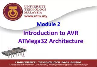
Module 2. Introduction to AVR ATMega32 Architecture. Processor Architecture & Organization. Architecture attributes of a system visible to a programmer these attributes have a direct impact on the logical execution of a program

E N D
Module 2 Introduction to AVR ATMega32 Architecture
Processor Architecture & Organization • Architecture • attributes of a system visible to a programmer • these attributes have a direct impact on the logical execution of a program • Instruction set, number of bits used for data representation, I/O mechanisms, addressing techniques • Design issue: whether a computer will have a specific instruction. • e.g. Is there a multiply instruction? 20112012-I
Processor Architecture & Organization • Organization • the operational units and their interconnections that realize the architectural specifications • (how features are implemented) • hardware details that are transparent to the programmers • Control signals, interfaces, memory technology • Design issue: how this instruction is to be implemented. • Is there a hardware multiply unit or is it done by repeated addition? • Split caches or unified cache 20112012-I
Processor Architecture & Organization • Many computer manufacturers offer a family of computer models, all with the same architecturebut with differences in organization. • This gives code compatibility (at least backwards) • All Intel x86 family share the same basic architecture • The IBM System/370 family share the same basic architecture • An architecture may survive many years, but its organization changes with the changing technology. • E.g. the IBM Systems/370 architecture, with few enhancements, has survived to this day as the architecture of IBM's mainframe product line. 20112012-I
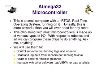
Introduction to Atmel AVR • Atmel Corporation is a manufacturer of semiconductors, founded in 1984. • Atmel introduced the first 8-bit flash microcontroller in 1993, based on the 8051 core. • In 1996, a design office was started in Trondheim, Norway, to work on the AVR series of products. • Its products include microcontrollers (including 8051derivatives and AT91SAMandAT91CAPARM-based micros), and its own Atmel AVRandAVR32architectures. 20112012-I
Introduction to Atmel AVR • The AVR architecture was conceived by two students at the Norwegian Institute of Technology(NTH) Alf-EgilBogenand VegardWollan. • TheAVRis amodified Harvard architecture8-bitRISCsingle chipmicrocontrollerwhich was developed by Atmelin 1996. The AVR was one of the first microcontroller families to use on-chipflash memory for program storage, as opposed toone-time programmable ROM, EPROM, orEEPROMused by other microcontrollers at the time. • The AVR is a modified Harvard architecture machine where program and data is stored in separate physical memory systems that appear in different address spaces, but having the ability to read data items from program memory using special instructions. • Atmel says that the name AVR is not an acronym and does not stand for anything in particular. The creators of the AVR give no definitive answer as to what the term "AVR" stands for.However, it is commonly accepted that AVR stands for Alf (EgilBogen) and Vegard (Wollan)'s Risc processor" 20112012-I
Von Neumann vs. Harvard architecture Harvard architecture CPU Data bus Data bus Code Memory Data Memory Address bus Address bus Control bus Control bus Data Memory Code Memory CPU Data bus Address bus Control bus Von Neumann architecture
Processor ISA: RISC versus CISC • RISC vs. CISC is a topic quite popular on the Net. Every time Intel (CISC) or Apple (RISC) introduces a new CPU, the topic pops up again. • Most PC's use CPU based on CISC architecture. For instance Intel and AMD CPU's are based on CISC architectures. • Many claim that RICS is the architecture of the future. • But even though RISC has been in the market since 1980, it hasn’t managed to kick CISC out of the picture, some argue that if it is really the architecture of the future it should have been able to do this by now. 20112012-I
AVR different groups • Classic AVR • e.g. AT90S2313, AT90S4433 • Mega • e.g. ATmega8, ATmega32, ATmega128 • Tiny • e.g. ATtiny13, ATtiny25 • Special Purpose AVR • e.g. AT90PWM216,AT90USB1287
Let’s get familiar with the AVR part numbers ATmega128 Atmel group Flash =128K ATtiny44 AT90S4433 Atmel Flash =4K Atmel Classic group Tiny group Flash =4K 20112012-I
ATMega32 Pin out & Descriptions Clears all the registers and restart the execution of program Provides supply voltage to the chip. It should be connected to +5 Port B Reference voltage for ADC Port A Supply voltage for ADC and portA. Connect it to VCC These pins are used to connect external crystal or RC oscillator Port C Port D 20112012-I
ATMega32 Pin out & Descriptions 20112012-I
ATMega32 Pin out & Descriptions 20112012-I
ATMega32 Pin out & Descriptions Digital IO is the most fundamental mode of connecting a MCU to external world. The interface is done using what is called a PORT. A port is the point where internal data from MCU chip comes out or external data goes in.They are present is form of PINs of the IC. Most of the PINs are dedicated to this function and other pins are used for power supply, clock source etc. ATMega32 ports are named PORTA, PORTB, PORTC, and PORTD. 20112012-I
ATMega32 Pin out & Descriptions 20112012-I
ATMega32 Pin out & Descriptions 20112012-I
ATMega32 Pin out & Descriptions Defining a pin as either Input or Output – The DDRx Registers LDI R20,0xFF ;R20 = 0b01110101 (binary) OUT PORTx,R20 ;PORTA = R20 OUT DDRx,R20 ;DDRA = R20 DDRx= 0b01110101; /* Configuring I/O pins of portb */ 20112012-I
ATMega32 Pin out & Descriptions Case 1 : To make a pin go high or low ( if it is an output pin)- Data Register PORTx 20112012-I
ATMega32 Pin out & Descriptions Pull-up resistors are used in electronic logic circuits to ensure that inputs to logic systems settle at expected logic levels if external devices are disconnected or high-impedance 20112012-I
ATMega32 Pin out & Descriptions Case 2 : To activate / Deactivate pull up resistors-Data Register PORTx 20112012-I
ATMega32 Pin out & Descriptions The PINx register gets the reading from the input pins of the MCU 20112012-I
AVR Architecture 20112012-I
ATMega32 Architecture • Native data size is 8 bits (1 byte). • Uses 16-bit data addressing allowing it to address 216 = 65536 unique addresses. • Has three separate on-chip memories • 2KB SRAM • 8 bits wide used to store data • 1KB EEPROM • 8 bits wide used for persistent data storage • 32KB Flash • 16 bits wide used to store program code • I/O ports A-D • Digital input/output • Analog input • Serial/Parallel • Pulse accumulator 20112012-I
ATMega32 Programmer Model: Memory • 2KB SRAM • For temporary data storage • Memory is lost when power is shut off (volatile) • Fast read and write • 1KB EEPROM • For persistent data storage • Memory contents are retained when power is off (non-volatile) • Fast read; slow write • Can write individual bytes • 32KB Flash Program Memory • Used to store program code • Memory contents retained when power is off (non-volatile) • Fast to read; slow to write • Can only write entire “blocks” of memory at a time • organized in 16-bit words (16KWords) 20112012-I
ATMega32 Programmer Model: Memory • AVR microcontrollers are Harvard architecture. This means, that in this architecture are separate memory types (program memory and data memory) connected with distinct buses. Such memory architecture allows processor to access program memory and data memory at the same time. This increases performance of MCU comparing to CISC architecture, where CPU uses same bus for accessing program memory and data memory. • Each memory type has its own address space: 20112012-I
ATMega32 Programmer Model: Program Memory Flash Memory Layout 20112012-I
ATMega32 Programmer Model: Data Memory EEPROM • ATmega32 contains 1024 bytes of data EEPROM memory. • It is organized as a separate data space, in which single bytes can be read and written. • The EEPROM has an endurance of at least 100,000 write/erase cycles. • Different chip have different size of EEPROM memory 20112012-I
ATMega32 Programmer Model: Data Memory The data memory is composed of three parts: • GPRs (general purpose registers), • Special Function Registers (SFRs), and • Internal data SRAM. 20112012-I
ATMega32 Programmer Model: Internal SRAM • Internal data SRAM is widely used for storing data and parameters by AVR programmers and C compilers. • Each location of the SRAM can be accessed directly by its address. • Each location is 8 bit wide and can be used to store any data we want. • Size of SRAM is vary from chip to chip, even among members of the same family. 20112012-I
ATMega32 Programmer Model: Registers 20112012-I
ATMega32 Programmer Model: Registers (GPRs) The fast-access Register file contains 32 x 8-bit general purpose working registers with a single clock cycle access time. This allows single-cycle Arithmetic Logic Unit (ALU) operation. In a typical ALU operation, two operands are output from the Register file, the operation is executed, and the result is stored back in the Register file –in one clock cycle.” 20112012-I
ATMega32 Programmer Model: Registers (GPRs) “Six of the 32 registers can be used as three 16-bit indirect address register pointers for Data Space addressing –enabling efficient address calculations. One of the these address pointers can also be used as an address pointer for look up tables in Flash Program memory. These added function registers are the 16-bit X-register, Y-register and Z-register, described later.” 20112012-I
ATMega32 Programmer Model: Registers (GPRs) • The R26..R31 registers have some added functions to their general purpose usage. These registers are 16-bit address pointers for indirect addressing of the Data Space. The three indirect address registers X, Y, and Z are shown above. • In the different addressing modes these address registers have functions as fixed displacement, automatic increment, and automatic decrement 20112012-I
ATMega32 Programmer Model:I/O Registers (SFRs) • The I/O memory is dedicated to specific functions such as status register, timers, serial communication, I/O ports, ADC and etc. • Function of each I/O memory location is fixed by the CPU designer at the time of design. (because it is used for control of the microcontroller and peripherals) • AVR I/O memory is made of 8 bit registers. • All of the AVRs have at least 64 bytes of I/O memory location. (This 64 bytes section is called standard I/O memory) • In other microcontrollers, the I/O registers are called SFRs (Special Function Registers) 20112012-I
ATMega32 Programmer Model: Registers (SP) 20112012-I
ATMega32 Programmer Model: Registers (SP) 20112012-I
ATMega32 Programmer Model: Registers (PC) • Program counter (PC, 16-bit) • Holds address of next program instruction to be executed • Automatically incremented when the ALU executes an instruction 20112012-I
ATMega32 Programmer Model: Registers (SR) 20112012-I
ATMega32 Programmer Model: Registers (SR) 20112012-I
ATMega32 Programmer Model: Registers (SR) 20112012-I
ATMega32 Programmer Model: Registers (SR) 20112012-I
ATMega32 Programmer Model: Registers (SR) 20112012-I
N H Z S V C I T SREG: CPU ALU Solution: $9C 1001 1100 - $9C 1001 1100 $00 0000 0000 R20 = $00 C = 0 because R21 is not bigger than R20 and there is no borrow from D8 bit. Z = 1 because the R20 is zero after the subtraction. H = 0 because there is no borrow from D4 to D3. Solution: $52 0101 0010 - $73 0111 0011 $DF 1101 1111 R20 = $DF C = 1 because R21 is bigger than R20 and there is a borrow from D8 bit. Z = 0 because the R20 has a value other than zero after the subtraction. H = 1 because there is a borrow from D4 to D3. Solution: 1 $9C 1001 1100 + $64 0110 0100 $100 1 0000 0000 R20 = 00 C = 1 because there is a carry beyond the D7 bit. H = 1 because there is a carry from the D3 to the D4 bit. Z = 1 because the R20 (the result) has a value 0 in it after the addition. Solution: 1 $38 0011 1000 + $2F 0010 1111 $67 0110 0111 R16 = 0x67 C = 0 because there is no carry beyond the D7 bit. H = 1 because there is a carry from the D3 to the D4 bit. Z = 0 because the R16 (the result) has a value other than 0 after the addition. Solution: $A5 1010 0101 - $23 0010 0011 $82 1000 0010 R20 = $82 C = 0 because R21 is not bigger than R20 and there is no borrow from D8 bit. Z = 0 because the R20 has a value other than 0 after the subtraction. H = 0 because there is no borrow from D4 to D3. R0 R1 R2 … … PC R15 R16 Instruction decoder R17 Instruction Register registers N H Z I S V C T R30 R31 Example: Show the status of the C, H, and Z flags after the subtraction of 0x9C from 0x9C in the following instructions: LDI R20, 0x9C LDI R21, 0x9C SUB R20, R21 ;subtract R21 from R20 Example: Show the status of the C, H, and Z flags after the addition of 0x9C and 0x64 in the following instructions: LDI R20, 0x9C LDI R21, 0x64 ADD R20, R21 ;add R21 to R20 Example: Show the status of the C, H, and Z flags after the subtraction of 0x23 from 0xA5 in the following instructions: LDI R20, 0xA5 LDI R21, 0x23 SUB R20, R21 ;subtract R21 from R20 Example: Show the status of the C, H, and Z flags after the addition of 0x38 and 0x2F in the following instructions: LDI R16, 0x38 ;R16 = 0x38 LDI R17, 0x2F ;R17 = 0x2F ADD R16, R17 ;add R17 to R16 Example: Show the status of the C, H, and Z flags after the subtraction of 0x73 from 0x52 in the following instructions: LDI R20, 0x52 LDI R21, 0x73 SUB R20, R21 ;subtract R21 from R20 ATMega32 Programmer Model: Registers (SR) SREG: Carry Interrupt Zero oVerflow Temporary Negative Sign N+V Half carry