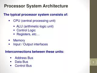
Introduction to Processor Architecture
Introduction to Processor Architecture. Contents. Introduction Processor architecture overview ISA(Instruction Set Architecture) RISC example (SMIPs) CISC example (Y86) Processor architecture Single-cycle processor example(SMIPs) Pipelining Control hazard Branch Predictor Data hazard


Introduction to Processor Architecture
E N D
Presentation Transcript
Contents • Introduction • Processor architecture overview • ISA(Instruction Set Architecture) • RISC example (SMIPs) • CISC example (Y86) • Processor architecture • Single-cycle processor example(SMIPs) • Pipelining • Control hazard • Branch Predictor • Data hazard • Cache memory
Processors • What is the processor? • What’s the difference among them?
Processor architecture and program • Understanding architecture, there’s more opportunity to optimize your program. • Let’s see some examples
1 • for(i=0 ; i<size ; i++) { for(j=0 ; j<size ; j++) { sum += array[i][j]; } } • for(j=0 ; j<size ; j++) { for(i=0 ; i<size ; i++) { sum += array[i][j]; } } Example1 2 Keyword : Cache
Example2 (1/2) 1 • for(i=0 ; i<size ; i++) { if(i%2 == 0) { action_even(); { else { action_odd(); } }
Example2 (2/2) 2 • for(i=0 ; i<size ; i += 2) { action_even(); } for(i=1 ; i<size ; i+= 2) { action_odd(); } Keyword : Branch predictor and pipeline
Von Neumann Architecture • Input -> process -> output model • Integrated Instruction Memory and Data Memory
Register file Basic components of x86 CPU Status Registers Program Counter Cache Memory Memory (external) Fetch Decode Execution Units Commit CPU pipeline
What is a register? Register file A simple memory element(s.t. edge triggered flip flops)
Register file • A collection of registers • 8 registers are visible • In fact, there are a lot of registers hided for other usages. ex) There are 168 registers in Intel’s Haswell
Program counter • Points the address of instruction that processor should execute next cycle. • %eip is the name of program counter register in X86. • Naming convention differs with ISA, Instruction Set Architecture
Status registers • Also a collection of registers • Boolean registers that represents processor’s status. • Used to evaluate conditions
Memory • Main memory, usually D-RAM • InVon Neumann architecture, instructions(codes) and data are on same memory module
CPU pipeline • Where actual operation occurs • Details will be explained later CPU pipeline Fetch Decode Execution Units Commit
Instruction Set Architecture (ISA) • How you actually talk to a Processor
Instruction Set Architecture (ISA) • Mapping between assembly code and machine code • What assembly codes will be included? • How to represent assembly codes in byte codes
Instruction • A command to processor to make processor perform specific task(s) • Ex1) Mov 4(%eax), %esp (x86) -> move the data in the address of (%eax) + 4, to %esp • Ex2) Irmovl %eax, $256 (y86) -> store the value 256 to the register eax
Representation of instructions 0 0 0 1 1 1 2 2 2 3 4 5 6 • Instructions are represented in byte codes • Pushl %ebx => 0xa01f • Irmovl %eax, $256 => 0x30f000010000 pushl popl irmovl
CISC vs RISC RISC(sMips) CISC(Y86)
CISC • Basic Idea : give programmers powerful instructions ; fewer instructions to complete a work • One instruction do multiple work • A lot of instructions! (over 300 in x86) • Many instruction can access memory • Variable instruction length
RISC • Basic Idea : Using simple instructions, write a complex program • Each instruction do only one task • Small instructionsset (about 100 in MIPS) • Only load and store instruction can access memory • Fixed instruction length
6 26 opcode target J-type Instruction formats 6 5 5 5 5 6 opcodersrt rd shamtfunc R-type • Only three formats but the fields are used differently by different types of instructions 6 5 5 16 opcodersrt immediate I-type
6 5 5 16 addressing mode opcodersrt displacement (rs) + displacement 31 26 25 21 20 16 15 0 6 5 5 5 5 6 0 rsrt rd 0 func rd (rs) func (rt) opcodersrt immediate rt (rs) op immediate Instruction formats • Computational Instructions • Load/Store Instructions rs is the base register rt is the destination of a Load or the source for a Store
6 5 5 16 opcoders offset BEQZ, BNEZ 6 5 5 16 opcoders JR, JALR 6 26 opcode target J, JAL Control instructions • Conditional (on GPR) PC-relative branch • target address = (offset in words)4 + (PC+4) • range: 128 KB range • Unconditional register-indirect jumps • Unconditional absolute jumps • target address = {PC<31:28>, target4} • range : 256 MB range jump-&-link stores PC+4 into the link register (R31)
Instruction formats 1 Byte 2 Bytes 5 Bytes 6 Bytes 0 0 0 0 1 1 1 1 2 2 2 3 3 4 4 5 5 6 • iCd : Instruction code • iFun: Function code • rA, rB : Register index
1 byte instructions – halt, nop halt 0 0 1 1 nop halt: Used as a sign of program termination - Changes processor state to halt (HLT) nop:No operation. Used as a bubble.
2 byte instruction – opl 0 1 2 OPl OPl: Perform 4 basic ALU operations; add, sub, and, xor - R[rB] <- R[rB] Op R[rA] - Condition flags are set depending on the result.
5 byte instruction – call 0 1 2 3 4 5 call dest call - R[esp] <- R[esp] - 4 (Update the stack pointer; move stack top) - M[esp] <- pc + 5 (Store the return address on the stack top) - pc <- Destination (Jump to Destination address)
6 byte instructions – rmmov, mrmov 0 0 1 1 2 2 3 3 4 4 5 5 6 6 rmmovl rA, Offset(rB) mrmovl Offset(rB), rA rmmovl: Store - target address =R[rB] + offset - M[target address] <- R[rA] mrmovl: Load - source address = R[rB] + offset - R[rA] <- M[source address]
Large sequential Logic Simplified version (a lot..) Output(register values) Clock Store Data Load program codes Memory
Sequential design Register File % EIP Memory Fetch Decode Execution Units Commit
Fetch unit Fetch % E I P 5) Give next instruction (Byte code) 1) Get PC 4) Update PC 3) Get next instruction 2) Require next instruction Memory
Decode Decode unit(1/2) 1) Truncate input Instruction 2) Fill information structure for execution iCd rA rB imm fCd Decode Combinational Logic Inst Type Target Register A Target Register B Immediate value Register value A Register value B … (depends on ISA)
Decode Decode unit(2/2) Decoded Instruction 3) Read register values Register Read Inst Type Inst Type Target Register A Target Register A Target Register B Target Register B Immediate value Immediate value … (depends on ISA) … (depends on ISA) Register value A Register value A Register value B Register value B Register File
Execute Execution unit(1/2) Executed Instruction Execute Combinational Logic Inst Type Inst Type Target Register Target Register A Memory Addr Target Register B Register Data Immediate value Memory Data Register value A ALU Register value B 1) Select input for ALU 3) Using ALU result, fill information structure for memory & register update 2) Perform appropriate ALU operation
Execute Execution unit(2/2) Executed Instruction (updated) Memory Operation Logic Inst Type Inst Type Target Register Target Register Memory Addr Memory Addr Register Data Register Data Memory Data Memory Data 5) Update the field (if load instruction executed) 4) Perform memory operations(Ld, St) Memory
Commit Commit unit Register Update Logic Inst Type Target Register Memory Addr Register Data Memory Data Register File
Single-Cycle SMIPS 2 read & 1 write ports SMIPs instructions are all 4 byte-long Register File PC Execute Decode +4 separate Instruction & Data memories Data Memory Inst Memory
Single-Cycle SMIPS module mkProc(Proc); Reg#(Addr) pc <- mkRegU; RFilerf <- mkRFile; IMemoryiMem <- mkIMemory; DMemorydMem <- mkDMemory; Rule doProc() let inst = iMem.req(pc); letdInst = decode(inst); letrVal1 = rf.rd1(validRegValue(dInst.src1)); letrVal2 = rf.rd2(validRegValue(dInst.src2)); leteInst = exec(dInst, rVal1, rVal2, pc); if(eInst.iType== Ld) eInst.data<- dMem.req(MemReq{op: Ld, addr:eInst.addr, data: ?}); else if(eInst.iType == St) let dummy <- dMem.req(MemReq{op: St, addr: eInst.addr, data: eInst.data}); if(isValid(eInst.dst)) rf.wr(validRegValue(eInst.dst), eInst.data); pc <= eInst.brTaken ? eInst.addr : pc + 4; endrule endmodule
Single-Cycle SMIPS Register File module mkProc(Proc); Reg#(Addr) pc <- mkRegU; RFilerf <- mkRFile; IMemoryiMem <- mkIMemory; DMemorydMem <- mkDMemory; PC Execute Decode +4 Data Memory Inst Memory • Declaration of components
Single-Cycle SMIPS Register File Rule doProc() let inst = iMem.req(pc); PC Execute Decode +4 Data Memory Inst Memory