Download
1 / 33
330 likes | 444 Views
This study explores optimizing the placement of Through Silicon Vias (TSVs) and shields to reduce TSV-TSV coupling in 3D integrated circuits. The solutions involve TSV spacing, shielding, and coupling-aware placement techniques. An algorithm based on force-driven placement is proposed for efficient TSV and shield positioning. Experimental results demonstrate the effectiveness of coupling-aware placement and shield insertion in minimizing wirelength and coupling force. Future work aims to integrate these techniques with transistor placement for further optimization.

E N D
Coupling-Aware Force Driven Placement of TSVs and Shields in 3D-IC Layouts Caleb Serafy and Ankur Srivastava Dept. ECE, University of Maryland
3D Integration • Vertically stack chips and integrate layers with vertical interconnects • Through Silicon Vias (TSVs) • Advantages: • Smaller footprint area • Shorter global wirelengths • Heterogeneous Integration • Disadvantages: • TSV-TSV coupling • TSV reliability • Increased power density • Trapped heat effect
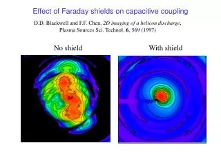
TSV-TSV Coupling • TSVs have large capacitance to substrate • Substrate is conductive: low noise attenuation • Coupling between TSVs must be minimized in order to maximize switching speed • SOLUTIONS: TSV spacing and TSV shielding
TSV spacing • Spacing between TSVs can reduce coupling • But requires large distance • Shield insertion can reduce coupling when spacing is small
TSV spacing • Spacing between TSVs can reduce coupling • But requires large distance • Shield insertion can reduce coupling when spacing is small d=12
TSV Shielding • Shielding: place a grounded conductor between two wires • EM waves cannot pass through shield, reducing coupling between wires • Guard ring is less effective with TSVs • TSVs require shielding throughout the thickness of the silicon substrate • use GND TSV as shield • Optimal shield placement requires chip-scale coupling models Analog Transistor
Previous Work [Serafy et. al GLSVLSI’13] • Geometric model of coupling • Circuit model of coupling too complex for chip-scale optimization • Developed model of S-parameter based on relative TSV positions • Used curve fitting on HFSS simulation data • Shield insertion algorithm • Based on fixed signal TSV locations, place shield TSVs to minimize coupling • Solved using MCF problem formulation • Avenue for improvement • Shield insertion cannot mitigate coupling if spacingis too small • Determine signal and shield positions simultaneously
Force-Driven Placement (FDP) Input: Fixed transistor placement Output:Placement for signal and shield TSVs • Objective: place signal and shield TSVs • Minimize some cost function • Force: derivative of cost function • Solution: find total force F=0 • Iteratively solve for F=0 and then update forces based on new placement
Forces • Wirelength (WL) Force: pulls objects towards position with optimal wirelength • Overlap Force: repels objects from one another when they overlap • Coupling Force: repels each signal TSV from its most highly coupled neighbor • Coupling evaluated using our geometric model • Shielding Force: Pulls shield TSVs towards the signal TSVs it is assigned to
Proposed Algorithm • Assumption: Transistor cells are already placed, limiting the possible locations of TSVs (whitespace) • Step 0: assign each signal TSV to a whitespace region • Step 1: perform coupling aware placement until equilibrium • Step 2: insert shields using our shield insertion method • Step 3: repeat coupling aware placement until equilibrium
Proposed Algorithm • Assumption: Transistor cells are already placed, limiting the possible locations of TSVs (whitespace) • Step 0: assign each signal TSV to a whitespace region • Step 1: perform coupling aware placement until equilibrium • Step 2: insert shields using our shield insertion method • Step 3: repeat coupling aware placement until equilibrium Coupling Force Repels TSVs WL force attracts TSVs back together Shield Reduces Coupling Force
Initial Placement • Each signal TSV must be assigned to a whitespace region • Once assigned TSVs cannot change regions • Objective: • Minimize wirelength • Constrain #TSV assigned to each region
Simulation Setup • Four Cases • Traditional Placement: WL and overlap force only • Placement with coupling force (CA) • Placement with shield insertion (SI) • CA+SI
Experimental Results • CA+SI required less shields than SI alone • Improvement due to CA+SI is greater than the sum of CA and SI alone • Change in total WL is an order of magnitude smaller than improvement to coupling
Illustrative Example Coupling Unaware Coupling Aware Without Shields Traditional CA With Shields CA+SI SI
Future Work • We have shown that signal and shield TSV placement must be done simultaneously • Also, coupling aware placement and shield insertion are complementary techniques • This approach should be integrated with transistor placement • Larger solution space • No assumptions about TSV and transistor placement • Optimize area • Instead of adding a fixed amount of whitespace for TSVs during transistor placement
Simulating Coupling • S-parameter (S): ratio of energy inserted into one TSV to energy emitted by another • Insertion loss, i.e. coupling ratio • HFSS: Commercial FEM simulator of Maxwell’s equations • HFSS data is used as golden data to construct model Our model is for specific physical dimensions. The modeling approach can be reapplied for different dimensions.
Modeling Approach • In HFSS: • Model two signal TSVs • Sweep distance d between them • Add a shield • Sweep d and shield distance y • x value does not change results • Add a second shield • Sweep y1 and y2 • Fit S(d,y1,y2) to HFSS data using curve fitting
Modeling Approach • In HFSS: • Model two signal TSVs • Sweep distance d between them • Add a shield • Sweep d and shield distance y • x value does not change results • Add a second shield • Sweep y1 and y2 • Fit S(d,y1,y2) to HFSS data using curve fitting
Modeling Approach • In HFSS: • Model two signal TSVs • Sweep distance d between them • Add a shield • Sweep d and shield distance y • x value does not change results • Add a second shield • Sweep (x1,y1) and (x2,y2) • Fit S(d,x1,y1,x2,y2) to HFSS data using curve fitting
Modeling Approach • In HFSS: • Model two signal TSVs • Sweep distance d between them • Add a shield • Sweep d and shield distance y • x value does not change results • Add a second shield • Sweep (x1,y1) and (x2,y2) • Fit S(d,x1,y1,x2,y2) to HFSS data using curve fitting
Modeling Approach • In HFSS: • Model two signal TSVs • Sweep distance d between them • Add a shield • Sweep d and shield distance y • x value does not change results • Add a second shield • Sweep (x1,y1) and (x2,y2) • Fit S(d,x1,y1,x2,y2) to HFSS data using curve fitting
Extension and Validation • Double shield model: • Add results from single shield model: S(d,y1)+S(d,y2) • Superposition is not an accurate model • Subtract overlap M(x1,y1,x2,y2) • Extension to n shields: • Add results from single shield models: S(d,y1)+…+S(d,yn) • Subtract overlap M(xi,yi,xj,yj) for each pair of shields • Assumes higher order overlap is negligible • Create random distributions of 3 and 4 shields • Compare HFSS results to model results • Average Error: • S3: 3.7 % S4: 9.4 % • S3: 1.6 dB S4: 4.6 dB
Shield Insertion Algorithm [Serafy et. al GLSVLSI’13] • For each signal TSV pair we identify the region where a shield could improve the coupling of that pair • Assign a shield to each TSV pair using MCF problem formulation • Objective: provide shielding for each TSV pair while using least number of shields • Take advantage of region overlap Good Solution Poor Solution
MCF Shield Insertion Algorithm From Serafy et. al GLSVLSI’13 • Each pair of signal TSVs defines a region • A set of positions that are good candidates for shielding that pair • MCF problem: assigns a shield to each TSV pair • Objective: Maximize ratio of shielding added to shielding required (shielding ratio) for each TSV pair while using least number of shields
MCF Problem Formulation From Serafy et. al GLSVLSI’13 • Region node for each TSV pair • Point node for each whitespace grid point • Point cost proportional to total shielding ratio • True cost of each shield is independent of amount of flow carried u = capacity c = cost Heuristic: After each iteration scale cost by number of units of flow carried in previous iteration
Placement Forces • FKOZ is the overlap force • Prevents a TSV from getting within the KOZ area of a transistor or another TSV • FWL is the wirelength force • Pushes each TSV towards its respective netbox • TSVs inside the netbox have minimal WL and FWL = 0 • FC is a new force which captures the coupling between two TSVs • Coupling force is proportional to the coupling between two TSVs • Each TSV has a coupling force from all other TSVs, but only the strongest coupling force is used to determine movement on each iteration • FShielding pushes shield TSVs towards each signal TSV they are assigned to A: all signal TSVs assigned to this shield
Why max(Fc) • Don’t let many loosely coupled TSVs overpower strongly coupled TSV