Download
1 / 21
210 likes | 427 Views
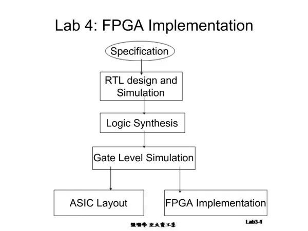
FPGA implementation of trapeziodal filters mid presentation. Instructor: Evgeniy Kuksin Preformed by: Ziv Landesberg Duration: 1 semester . Project goal from presentation.

E N D
FPGA implementation of trapeziodal filtersmid presentation Instructor: EvgeniyKuksin Preformed by: ZivLandesberg Duration: 1 semester
Project goal from presentation • Create a FIR filter that can process pulses from photon counting detectors and perform Peak Detection using NI Labview FPGA.
Progress so far • Plan and build trapeziodal shaper in Labview • Create the trapeziodal shaper on the FPGA and test it at low clock rate • Test the system at high clock rate (150MHz) , still on computer
Future stages • Test the filter on signal recived from analog signal generator • Implement the pulse detector
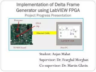
System description Photons FPGA - Readout To PC Peak Detector Shaper ADC +
Project Block Diagram • A\D • NI 5761 • 14 bit • 150 MHz FPGA(150MHz) • Signal generator • (Preamplifier emulator)
Reasons to use Trapeziodal shaper over other shapers • Trapezoidal can achive optimal noise performance from signal. Trapezoidal Shaper, unlike many analog pulse shaper, immune to “ballistic deficit”, that causes energy distortion in the spectrum.
Coefficients calculation • The Coefficients were calculated by the method at the article of “On nuclear spectrometry pulses digital shaping and processing” , the biexponential pulse part. the method is to inverse the transfer function of the pulse(making it a digital delta) , and then convolute the delta with a trapezoid. Due to the fect that both the inverse function of the pulse and the trapezoid were finite length , the resulted filter was FIR.
The signal generation • The input signal was generated at 2 main stages : • 1) create an array with Poisson distributed digital delta’s in it. It was done by the Poisson noise generator, that each event was transformed to delta, and each none event was transformed to zero. • 2 ) transfer the deltas to linear rising- exponential decaying pulse, was done simply by convoluting the array with the response of such pulse(with cut-off values lower than exp(-10 ))
Build filter The building of the filter in Labview was done using the fir template already existing in the program. So first stage was to create a fds file to generate filter from. The second stage was to use the automatic filter generation.
Project requirements (unchanged) • FPGA that can be programmed using LABVIEW • Analog signal generator • A\D convertor
Estimated time lines Yellow- partially done Red- need to be done