Download
1 / 9
90 likes | 182 Views
Discussing developments around PS 10 MHz system, including hardware changes and interface clarification between low-level and high-power RF. Presenting status updates, such as software validation and hardware design progress. Exploring new features like digital feedback board and AVC surveillance. Detailing additional hardware for improved feedback functionality post-LS1.

E N D
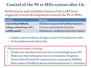
Control of the PS 10 MHz system after LS1 • Performance and reliability issues of the LLRF have triggered several developments around the PS 10 MHz: • Implies some hardware changes on low-level and power sides • To be implemented coherently • Objectives of today’s meeting: • Clarify new interfaces between low-level and high-power RF • Make sure that nothing has been overlooked or forgotten • Ensure that all interlock requirements are properly fulfilled • Show status of feedback board and measurements ( Damien)
10 MHz voltage program selector (matrix) • The existing hardware will be replaced by a digital voltage program generation and relay timings per cavity • No hardware selection system, matrix settings virtual • Signals are distributed as differential serial CVORB data streams PA.GSV10GLOBAL PA.GSV10RED Hereward damp. (analog/digital) Voltage program C10-11 PA.GSVMODC11 PA.GSVMODC36 Voltage program C10-36 PA.GSVMODC96 Voltage program C10-96 Vprog (C10-36) = [(GSV10GLOBAL GSV10RED) + Hereward] GSVMODC36
Signals today and with new 10 MHz matrix • Present status: • Software part successfully validated during 2013 run (thanks to Pablo Pera Mira from BE-CO-DA) • Board designs of hardware quasi finished (‘bureau d'études’); prototypes expected in March/April 2013
Present set-up of AVC and 1-turn feedback • Now: Loop + Interlock Drive path Return path (AVC) 1-turn feedback Final amplifier and cavity From beam controls M. Haase
New 1-turn delay feedback + AVC loop • Digital feedback board: • Filters and delays for 1-turn feedback • Digital loop implementation for AVC • No equipment protection functions • AVC surveillance board: • Interlock/protection functionality • Analog test outputs for Vprog, Vdet, etc. • Plugin compatibility with existing AVC • Interface between boards: • AVC surveillance generates DAC INHIBIT to shutdown the DACs of feedback board • No soft- or firmware involved Damien’s presentation Matthias + apprentice
New 1-turn delay feedback + AVC loop Drive path Return path (AVC and 1-turn FB) From cavity h (CVORB) Vprog (CVORB) To cavity via RF switch From beam controls Gap relay timings
Additional hardware • AVC surveillance (NIM) replacing present AVC • LHC-type VME crates (like test installation) per tuning group • Feedback boards (3, 3, 4, 1) • CTRV timing boards (1 or 2) • Men A20 processor • Crate Management module • Cabling (FSU) • Technical network • Clock h = 200 distribution • Differential data cabling of Vprog, harmonic number and phase (?) • Timing cables for gap relays (local?) • Location of VME crates? • Detailed cabling lists to be established soon
Summary • Important changes and modifications the signal distribution and the RF loops/feedbacks during LS1 • Objective: Start up with new • 10 MHz matrix, • 1-turn feedbacks and • Voltage control loops • with present performance at least. • Keep backwards compatibility of interlock signals • No compromises on equipment protection • Lots of potential for further improvements and new features following operational experience after LS1 start-up: • Impedance reduction with increased 1-turn feedback gain • Phase control loop around each cavity • …?