Download
1 / 43
430 likes | 544 Views
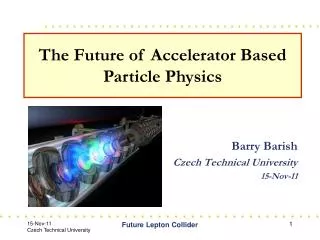
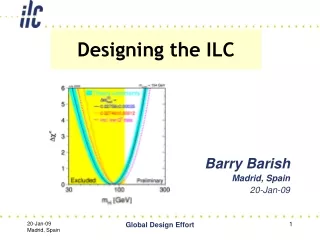
Global Design Effort Director’s Report. Grooved Insert for CesrTA Wiggler. Barry Barish PAC - Prague 14-Nov-11. Systems Tests. Fermilab NML: RF Unit Test Facility. GDE Status & Plans. Update on ILC accelerator R&D The Technical Design Report Top level changes

E N D
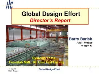
Global Design Effort Director’s Report Grooved Insert for CesrTA Wiggler Barry Barish PAC - Prague 14-Nov-11 Systems Tests Fermilab NML: RF Unit Test Facility Global Design Effort
GDE Status & Plans • Update on ILC accelerator R&D • The Technical Design Report • Top level changes • Baseline Technical Reviews ; PM level changes • TDR Scope and Plans • Cost Estimate • Project Implementation Planning • ILC Systems Tests • Post-TDR planning • Japan CFS News and Plans Global Design Effort
Update on ILC accelerator R&D SCRF ATF-2 Electron Cloud Global Design Effort
Major R&D Goals for Technical Design SCRF High Gradient R&D - globally coordinated program to demonstrate gradient by 2010 with 50%yield; improve yield to 90% by TDR (end 2012) Manufacturing: plug compatible design; industrialization, etc. Systems tests: FLASH; plus NML (FNAL), STF2 (KEK) post-TDR Test Facilities ATF2 - Fast Kicker tests and Final Focus design/performance EARTHQUAKE RECOVERY CesrTA - Electron Cloud tests to establish damping ring parameters/design and electron cloud mitigation strategy FLASH – Study performance using ILC-like beam and cryomodule (systems test) Global Design Effort Global Design Effort
The ILC SCRF Cavity • Achieve high gradient (35MV/m); develop multiple • vendors; make cost effective, etc • Focus is on high gradient; production yields; cryogenic • losses; radiation; system performance Global Design Effort
Global Plan for ILC Gradient R&D New baseline gradient: Vertical acceptance: 35 MV/m average, allowing ±20% spread (28-42 MV/m) Operational: 31.5 MV/m average, allowing ±20% spread (25-38 MV/m) Global Design Effort
Cavity Gradient Milestone Achieved TDR Goal 2010 Milestone • Toward TDR goal • Field emission; mechanical polishing • Other progress Global Design Effort
ATF2 – Beam size/stability and kicker tests IP Shintake Monitor Final Doublet Global Design Effort
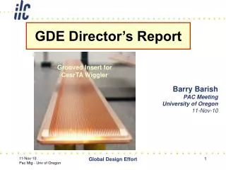
eCloud R&D • Mitigating Electron Cloud • Simulations – electrodes; coating and/or grooving vacuum pipe • Demonstration at CESR critical tests Global Design Effort
CesrTA - Wiggler Observations 0.002”radius Electrode a best performance Global Design Effort IWLC2010 - CERN, Geneva, Switzerland
Proposed ILC Mitigation Scheme Global Design Effort
The Technical Design Report Top level changes Baseline Technical Reviews (lower level changes) TDR Scope and Plans (Walker) Cost Estimate (Dugan) Project Implementation Planning (Paterson) Global Design Effort
Establishing Baseline for the TDR Global Design Effort
Proposed Design changes for TDR RDR SB2009 • Single Tunnel for main linac • Move positron source to end of linac *** • Reduce number of bunches factor of two (lower power) ** • Reduce size of damping rings (3.2km) • Integrate central region Global Design Effort
Technical Design Phase and Beyond change control process AAP PAC Physics TDP Baseline Technical Design TDR RDR Baseline SB2009 evolve TDP-2 TDP-1 Beijing Workshop CERN Workshop Change Request RDR ACD concepts R&D Demonstrations AD&I studies 2009 2010 2011 2012 2013 Global Design Effort
Technical Volumes 2007 2011 2013* ~250 pagesDeliverable 2 TDR Part I: R&D TDR Part II:BaselineReferenceReport ~300 pagesDeliverables 1,3 and 4 AD&I ILC Technical Progress Report (“interim report”) Technical Design Report Reference Design Report * end of 2012 – formal publication early 2013 Nick Walker - PAC, Prague
ILC Project Implementation Planning • Contents • Executive Summary • Governance • Funding Models • Project Management • Host Responsibilities • Siting Issues • In-Kind Contribution Models • Industrialisation and Mass Production of the SCRF Linac Components • Project Schedule • Future Technical Activities Global Design Effort
Project Implementation Planning Global Design Effort
(Global) Mass Production (SCRF) PIP Governance TLCC-1 Global S1 TDP-2 • Critically important TDP2 activity • Learn from XFEL experience • 5% ILC • Learn from LHC experience • Develop realistic models on which to base cost estimate • With industry SCRF Global Design Effort
KEK Industrial R&D Pilot Plant 19m x 14m ISO class-5 clean room Chemical Polish room Electron Beam Welder Press machine Triming machine work together with industry to develop cost-effective cavity production techniques Global Design Effort
Systems Tests TDR Post - TDR Global Design Effort
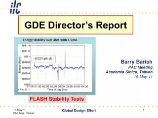
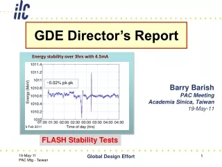
FLASH: Stability • 15 consecutive studies shifts (120hrs), and with no downtime • Time to restore 400us bunch-trains after beam-off studies: ~10mins • Energy stability with beam loading over periods of hours: ~0.02% • Individual cavity “tilts” equally stable Energy stability over 3hrs with 4.5mA ~0.02% pk-pk Global Design Effort 9 Feb 2011
Fermilab – NML SRF Schedule Global Design Effort
KEK – STF Plans for Cryomodule Tests Global Design Effort
TDR Cost Estimate “Value Costs” - Plans and Scope Comparisons with RDR costs Global Design Effort
TDR Cost estimate: Scope • The cost estimate covers only the costs for the 500 GeV design as detailed in the TDR, to be expended during the 8 year construction period. • Costs for project engineering and design, R&D prior to construction authorization, commissioning, pre-operation, operation, and de-commissioning are not included. • Costs for upgrading the machine to 1 TeV are not included in the baseline estimate, except the cost of those systems which would be very difficult to provide after construction of the 500 GeV machine. • An approximate cost for the 1 TeV upgrade will be provided separately. ILC PAC
OECD PPP (Yen/USD)-annual average by year PPP = Purchasing Power Parity EX-exchange rate GDP: PPP based on all goods/services in GDP of each region M&E: PPP based on machinery and equipment Const: PPP based on civil construction Full PPP determinations were done for 2005 and 2008; other year points based on GDP inflation rates Global Design Effort
Post TDR Extending the energy of the ILC Continued R&D – especially SCRF Organization? (ILCSC) Global Design Effort
ILC possible timeline 2010 2011 2012 2013 2014 2015 2016 2017 2018 CY Technical Design Report complete Baseline established Decision to proceed TDR reviews ILC Technical design & R&D program Site/host established Site EOI’s Cost Estimating SRF system tests Project Implementation Plan complete XFEL operation Physics Run 1 Interconnect repair Physics Run 2 LHC Existence of low-lying SUSY known Higgs energy scale known timegap Global Design Effort
ILC possible timeline 2010 2011 2012 2013 2014 2015 2016 2017 2018 CY Technical Design Report complete Baseline established Decision to proceed TDR reviews ILC Technical design & R&D program Site/host established Site EOI’s Cost Estimating SRF system tests Project Implementation Plan complete XFEL operation Physics Run 1 Interconnect repair Physics Run 2 LHC Existence of low-lying SUSY known Higgs energy scale known timegap Global Design Effort
Post – TDR (ILCSC) Global Design Effort
Extending the reach of the ILC • ICFA LC Parameters subcommittee (2003 and 2006) Global Design Effort
Extending the reach of the ILC • Upgrade option for study: • - Power < 300MW AC • - New linac grad = 45 MV/m • - Q0 = 2 1010 • Strawman TeV parameters • Post-TDR program: • Improve cavity gradient • Cost effective production • Flexibilty: Initial ILC energy: higher or lower energy, as informed by LHC results Global Design Effort
Post-TDR ILC Interim Goals & Organization • GDE will have successfully completed its mandate after TDR & PIP delivered + reviewed (mid-2013 at latest + transition) • What should follow GDE (mandate and organization) for an interim 3-5 year period? (ILCSC – Bagger) • GDE position paper submitted to ILCSC Aug 2011. The paper addresses: • Technical Goals proposed for 2012+ program? • Value engineering; Continued system demonstrations; Increasing energy reach; + • Organizational Issues for 2012+ post GDE? • What are primary GDE assets that should be preserved? • What are the primary GDE weaknesses that should be improved? • We must define what systems tests must demonstrate for each LC option before construction of a LC? ICFA?? Global Design Effort
Two Candidate Sites in Asia/Japan • GDE-CFS group visited two sites, • Oct., 2011
Common Features Courtesy: M. Miyahara ILC Cavity Industrialization
‘Bread Shape’ under Study Cost-and time-effective in Japan
Conclusions • The major R&D milestones for TDR are essentially in-hand • The Technical Design Report will be a self-contained comprehensive R&D report; with a design based on new baseline; a new value costing; and a section on project implementation planning • We seek your advice / concurrence on our system tests goals and program • Post–TDR program is being planned: extend energy reach; complete systems tests; evolve design based on technology development and LHC results Global Design Effort