Download
1 / 62
620 likes | 804 Views
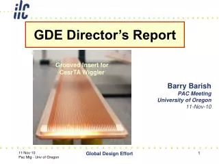
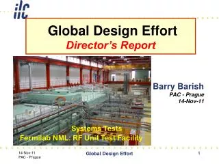
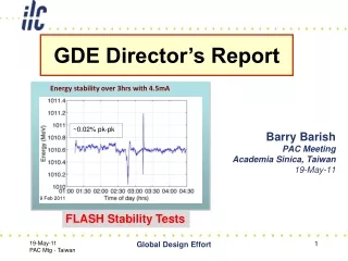
GDE Director’s Report. Grooved Insert for CesrTA Wiggler. Energy stability over 3hrs with 4.5mA. Barry Barish PAC Meeting Academia Sinica, Taiwan 19-May-11. ~0.02% pk-pk. FLASH Stability Tests. 9 Feb 2011. Outline. Responses to Nov 2010 PAC Report Update on ILC accelerator R&D

E N D
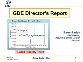
GDE Director’s Report Grooved Insert for CesrTA Wiggler Energy stability over 3hrs with 4.5mA Barry Barish PAC Meeting Academia Sinica, Taiwan 19-May-11 ~0.02% pk-pk FLASH Stability Tests Global Design Effort 9 Feb 2011
Outline • Responses to Nov 2010 PAC Report • Update on ILC accelerator R&D • Plans and Scope of for the TDR • TDR Baseline • TDR Phase 2 plans • Scope and Contents of the TDR • Future beyond 2012 Global Design Effort
PAC Report (Nov 2010) 4. PAC Summary and Recommendations General • The PAC is very impressed by the progress made in both accelerator and detector areas since the previous PAC meeting; the Committee thanked the speakers for the high quality of their presentations. ok • It is important that consideration be given by ILCSC, GDE and RD to maintaining global coherence of the ILC accelerator and detector R&D efforts past the 2012 design report. strongly agree • The ILC-CLIC collaborative activities in both the accelerator and detectors are growing, and the PAC views this positively. ok Global Design Effort
PAC Report (Nov 2010) – continued Accelerator • The PAC is very pleased to note that the GDE’s approach to cavity production in the ILC construction phase intends to follow the successful example of the LHC in the industrialization of complex superconducting components, rather than that of the much smaller-scale XFEL project. see update by Yamamoto following industrial visits, etc • The PAC is very impressed by the recent progress on SCRF cavity gradients; 9 out of 10 cavities from one manufacturer meeting the nominal ILC gradient requirement is an outstanding achievement. thankyou • There is a need to pay attention to the issue of field emission in the SCRF cavities. agree ---- see Geng report Global Design Effort
PAC Report (Nov 2010) – continued • The Committee is impressed with the progress made so far on the R&D programs at existing accelerator facilities. • The FLASH 9 ma experiment is a good demonstration that the ILC accelerator parameter goals are realistic. The PAC recommends that ILCSC make efforts to ensure that the needed future FLASH beam time becomes available. agree – nothing new to report (update by Ross) • ATF has achieved success with the fast kicker performance reaching ILC requirements; the small beam size goal is still to be achieved. recovery from earthquake still uncertain (see Tauchi report) • The CesrTA program on electron cloud studies is excellent, and is also very valuable for accelerators other than the ILC. It is essential that simulation codes are benchmarked against experimental data before the end of this program. agree – (see Palmer report) Global Design Effort
PAC Report (Nov 2010) – continued • The PAC endorses the methodology for GDE design change control which is now in place, and which appears to be working well. The Committee also notes positively the membership of a detector physicist on the GDE Change Evaluation Panel. baseline is now established through this process for the TDR • The PAC sees significant progress in addressing the issues raised by the SB2009 proposals, including progress towards resolution of several hardware questions following from the proposals. The Committee is gratified to observe the greatly improved collaboration with the detector community in SB2009 discussions. we agree • At the previous PAC meeting, the Committee was concerned with the lack of progress on positron source issues, but is pleased that this lacuna now appears to be well covered. There seems to be increased interest within the detector community in the additional physics that can be realized with polarization of the ILC positron beam. no new report this meeting Global Design Effort
Outline • Responses to Nov 2010 PAC Report • Update on R&D • Plans and Scope of for the TDR • TDR Baseline • TDR Phase 2 plans • Scope and Contents of the TDR • Future beyond 2012 Global Design Effort
Major R&D Goals for Technical Design SCRF High Gradient R&D - globally coordinated program to demonstrate gradient by 2010 with 50%yield; improve yield to 90% by TDR (end 2012) Manufacturing: plug compatible design; industrialization, etc Future systems tests: NML (FNAL), STF2 (KEK) Test Facilities ATF2 - Fast Kicker tests and Final Focus design/performance CesrTA - Electron Cloud tests to establish damping ring parameters/design and electron cloud mitigation strategy FLASH – Study performance using ILC-like beam and cryomodule Global Design Effort Global Design Effort
SCRF Status/Progresshigh gradient cavitiessystem testsindustrialization See Geng, Hayano, Yamamoto Global Design Effort
The ILC SCRF Cavity • Achieve high gradient (35MV/m); develop multiple • vendors; make cost effective, etc • Focus is on high gradient; production yields; cryogenic • losses; radiation; system performance Global Design Effort
Global Plan for ILC Gradient R&D New baseline gradient: Vertical acceptance: 35 MV/m average, allowing ±20% spread (28-42 MV/m) Operational: 31.5 MV/m average, allowing ±20% spread (25-38 MV/m) Global Design Effort
Cavity Gradient Milestone Achieved TDR Goal 2010 Milestone See Geng • Toward TDR goal • Field emission; mechanical polishing • Other progress Global Design Effort
Comparison of cavity performance ave. Eacc,max VT : 30 MV/m 1 cav : 27 MV/m 7 cav : 26 MV/m C D D AES004 ACC011 Z108 Z109 MHI-05 MHI-07 D : Detune C : Coupler MHI-06 MHI-09 FNAL DESY KEK Global Design Effort See Hayano
Test Facilities: FLASHSCRF accelerator tests See Ross Global Design Effort
Example Experimental Results • Flat gradient solution achieved • 4.5 mA beam Gradient Tilts vs Beam Current (ACC7) +5 +3 ~2.5% 0 Gradient change over 400us (%) -3 -5 Intended working point 3 4 5 1 2 Beam Current (mA) • Characterisation of solution by scanning beam current • model benchmarking Global Design Effort
FLASH: Stability • 15 consecutive studies shifts (120hrs), and with no downtime • Time to restore 400us bunch-trains after beam-off studies: ~10mins • Energy stability with beam loading over periods of hours: ~0.02% • Individual cavity “tilts” equally stable Energy stability over 3hrs with 4.5mA ~0.02% pk-pk Global Design Effort 9 Feb 2011
Test Facilities: Cesr-TA eCloudbroad accelerator applications See Palmer Global Design Effort
eCloud R&D • Mitigating Electron Cloud • Simulations – electrodes; coating and/or grooving vacuum pipe • Demonstration at CESR critical tests Global Design Effort
Mitigation - Simulation Studies Global Design Effort
CesrTA - Wiggler Observations 0.002”radius Electrode a best performance Global Design Effort IWLC2010 - CERN, Geneva, Switzerland
Proposed ILC Mitigation Scheme Global Design Effort
Test Facilities: ATF-2large international collaboration See Tauchi Global Design Effort
ATF2 – Beam size/stability and kicker tests IP Shintake Monitor Final Doublet Global Design Effort
ATF Recovery Plan Global Design Effort
Outline • Responses to Nov 2010 PAC Report • Update on R&D • Plans and Scope of for the TDR • TDR Baseline • TDR Phase 2 plans • Scope and Contents of the TDR • Future beyond 2012 Global Design Effort
Design UpdateGlobal Design and Decision Making(SB2009) N Walker for baseline details Global Design Effort
Establishing Baseline for the TDR Global Design Effort
Proposed Design changes for TDR RDR SB2009 • Single Tunnel for main linac • Move positron source to end of linac *** • Reduce number of bunches factor of two (lower power) ** • Reduce size of damping rings (3.2km) • Integrate central region • Single stage bunch compressor Global Design Effort
Technical Design Phase and Beyond change control process AAP PAC Physics TDP Baseline Technical Design TDR RDR Baseline SB2009 evolve TDP-2 TDP-1 Beijing Workshop CERN Workshop Change Request RDR ACD concepts R&D Demonstrations AD&I studies 2009 2010 2011 2012 2013 Global Design Effort
Top Level Change Control Process keywords: open, transparent Global Design Effort Global Design Effort 34 34
TLCC Process Increased Physics and detector input / representation in the process • Baseline Assessment Workshops • Face to face meetings • Open to all stakeholders • Plenary Global Design Effort Global Design Effort 35
TLCC Process • Formal Director Approval • Change evaluation panel • Chaired by Director • Final formal step (recommended by AAP) • Change Evaluation Panel • Chaired by director • Experts to evaluate impact on performance, cost, schedule, risk • F. Asiri, K. Buesser*, J. Gao, P. Garbincius, T. Himel, K. Yokoya + J Brau* for BAW-3,4 • Decision by Director • Accepts – becomes baseline; guidance in decision memo • Rejects – sent back for further work with comments Global Design Effort Global Design Effort 36 36
Proposals Received Global Design Effort
TLCC Process Global Design Effort Global Design Effort 38
TLCC Process Global Design Effort Global Design Effort 39
2nd Baseline Assessment Workshop'Reduced Beam Parameter set’ and ‘Positron Source Location’ • Result • Assessment of technical implication, proposed in SB2009, • Impact across system interfaces, cost, and schedule • Consensus to be discussed with the GDE and Physics/Detector collaborators, • Proposals submitted for Top Level Change Control (TLCC) evaluation panel (chaired by GDE Director) • Both proposals APPROVED Global Design Effort
TLCC Process Global Design Effort Global Design Effort 41
TLCC Process Global Design Effort Global Design Effort 42
Outline • Responses to Nov 2010 PAC Report • Update on R&D • Plans and Scope of for the TDR • TDR Baseline • TDR Phase 2 plans • Scope and Contents of the TDR • Future beyond 2012 Global Design Effort
Plans through 2012--------------Technical Design Report (TDR) Global Design Effort
Technical Design Phase 2 • Timescale: Produce final reports end of 2012 • Technical Design (TDR) • Project Implementation (PIP) • First goal: Technical Design (TDR) • SCRF – S0 gradient; S1 Global Tests continue past 2012 • Detailed technical design studies from new baseline • Updated VALUE estimate and schedule. • Remaining critical R&D and technology demonstration (CesrTA complete; ATF-2; FLASH; etc) • Second Goal: Project Implementation Plan (PIP) • Studies of governance; siting solicitation and site preparations; manufacturing; etc Global Design Effort
Scope of TDR and supporting work (1) Technical Design Report Outline • Part 0: Executive Summary • An overview of Parts 1-4 that is written for a less technical audience, such as decision makers and other branches of science. • Part 1: TD phase R&D (extension/update of the Interim Report (IR), but more conclusive) • Introduction/Overview • SCRF Technology • Accelerator Systems • Concluding (or summarising) chapter. Global Design Effort
Scope of TDR and supporting work (2) • Part 2: Design report Equivalent (replacement) for the RDR. May well draw on RDR text were it has not significantly changed, although much will need to be updated. • Introduction • Overview, layout and parameters • Main linac • Sources • Damping Rings • RTML / bunch compressors • BDS/MDI • CFS • TeV upgrade path • Cost and schedule Global Design Effort
Scope of TDR and supporting work (3) • Part 3: Risk analysis and post 2012 work Identified remaining technical risk should support the future R&D programme, in the same way that the identified RDR risk set the scope of the TDP work. • R&D: SCRF - ultra-high gradient (relates to TeV upgrade); SCRF System tests; Positron source related, etc • Project engineering : Design for manufacture; value engineering; site development (detailed CFS engineering) • Technical (Performance) Risk Analysis: Where are the extrapolations? How much is the extrapolation? What is the risk of not achieving extrapolation? What is the impact of failure? What is the mitigation strategy? • Part 4: Implementation Plan Global Design Effort
Starting Point is the RDR Costs Global Design Effort
Impact of Baseline Changes Global Design Effort