Introducing the CMS Trigger
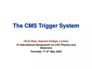
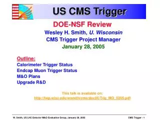
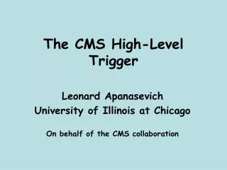
Introducing the CMS Trigger. J-Term at the LHC Physics Center Wesley H. Smith U. Wisconsin - Madison CMS Trigger Project Manager January 11, 2006 Outline: Physics & Conditions at the LHC Trigger Architecture Calorimeter, Muon & Global Trigger Systems Trigger Physics Performance

Introducing the CMS Trigger
E N D
Presentation Transcript
Introducing the CMS Trigger • J-Term at the LHC Physics Center Wesley H. Smith U. Wisconsin - Madison CMS Trigger Project Manager January 11, 2006 • Outline: • Physics & Conditions at the LHC • Trigger Architecture • Calorimeter, Muon & Global Trigger Systems • Trigger Physics Performance • Trigger Distribution & Synchronization • Higher Level Triggers • This talk is available on: • http://cmsdoc.cern.ch/cms/TRIDAS/tr/06/01/Smith_trig_LPC_jan06.pdf
LHC Physics & Event Rates • At design L = 1034cm-2s-1 • 17 pp events per 25 ns crossing • ~ 1 GHz input rate • “Good” events contain ~ 20 bkg. events • 1 kHz W events • 10 Hz top events • < 104 detectable Higgs decays/year • Can store ~ 100 Hz of events • Select in stages (at L = 1034 ): • Level-1 Triggers • 1 GHz to 100 kHz • High Level Triggers • 100 kHz to 100 Hz • Build in stages, start at: • Level-1: 50 kHz output • HLT: 100 Hz output
Discovery Physics at the LHC • Physics at EWSB scale (250 GeV) • 115 < Mhiggs < 200 GeV • Couplings to W (80), Z (91) • Lepton PT ~ 40 GeV • TeV scale supersymmetry • Multiple leptons, jets and LSPs (missing PT), PT < 100 GeV • QCD Background • Jet ET ~ 250 GeV Rate = 1 kHz • Jet fluctuations electron BG • Decays of p, k, B muon BG
Overview of Trigger & DAQ Challenges: 1 GHz of Input Interactions Beam-crossing every 25 ns with ~17 interactions produces over 1 MB of data Archival Storage at about 100 Hz of 1 MB events 40 MHz 16 Million channels DETECTOR CHANNELS COLLISION RATE 3 Gigacell buffers LEVEL-1 TRIGGER Charge Time Pattern Energy Tracks 100- 50 kHz 1 MB EVENT DATA 1 Terabit/s 200 GB buffers READOUT ~ 400 Readout memories 50,000 data channels EVENT BUILDER. A large switching network (400+400 ports) with total throughput ~ 400Gbit/s forms the interconnection between the sources (deep buffers) and the destinations (buffers before farm CPUs). 500 Gigabit/s SWITCH NETWORK ~ 400 CPU farms EVENT FILTER. A set of high performance commercial processors organized into many farms convenient for on-line and off-line applications. 100 Hz FILTERED 5 TeraIPS EVENT Computing Services Gigabit/s Petabyte ARCHIVE SERVICE LAN
CMS Level-1 Trigger & DAQ • Overall Trigger & DAQ Architecture: 2 Levels: • Level-1 Trigger: • 25 ns input • 3.2 s latency UXC USC Interaction rate: 1 GHz Bunch Crossing rate: 40 MHz Level 1 Output: 100 kHz (50 initial) Output to Storage: 100 Hz Average Event Size: 1 MB Data production 1 TB/day
L1 Trigger Locations • Underground Counting Room • Central rows of racks fortrigger • Connections via high-speed copper links to adjacent rows of ECAL & HCAL readout racks with trigger primitive circuitry • Connections via opticalfiber to muon trigger primitive generatorson the detector • Optical fibersconnected via“tunnels” to detector(~90m fiber lengths) 7m thickshieldingwall USC55 Rows of Racks containing trigger & readout electronics
Calorimeter Trig. Algorithms • Electron (Hit Tower + Max) • 2-tower ET + Hit tower H/E • Hit tower 2x5-crystal strips >90% ET in 5x5 (Fine Grain) • Isolated Electron (3x3 Tower) • Quiet neighbors: all towerspass Fine Grain & H/E • One group of 5 EM ET < Thr. • Jet or ET • 12x12 trig. tower ET sliding in 4x4 steps w/central 4x4 ET > others • : isolated narrow energy deposits • Energy outside veto pattern sets veto • Jet if all 9 4x4 region vetoes off
CMS Calorimeter Geometry EB, EE, HB, HE map to 18 RCT crates Provide e/g and jet, t, ET triggers 2 HF calorimeters map on to 18 RCT crates 1 trigger tower (.087 x .087) = 5 x 5 ECAL xtals = 1 HCAL tower
ECAL Endcap Geometry • Map non-projective x-y trigger crystal geometry onto projective trigger towers: Individualcrystal +Z Endcap -Z Endcap 5 x 5 ECAL xtals 1 HCAL tower in detail
Calorimeter Trigger Overview(in underground counting room -- USC55) , 0 < < 3.0 , 3.0 < < 5.0
ECAL Trigger Primitives- Lisbon/Palaiseau(LLR) OD TTC TCS Trigger Tower 25 Xtals (TT) Level 1 Trigger (L1A) L1 @100 kHz CCS (CERN) Regional CaloTRIGGER SLB (LIP) TCC (LLR) Global TRIGGER Trigger Tower Flags (TTF) Trigger primitives @800 Mbits/s Trigger Concentrator Card Synchronisation & Link Board Clock & Control System Selective Readout Processor Data Concentrator Card Timing, Trigger & Control Trigger Control System SRP (CEA DAPNIA) Selective Readout Flags (SRF) Data path @100KHz (Xtal Datas) DAQ DCC (LIP) From : R. Alemany LIP
ECAL Trigger Primitives Test beam results (45 MeV per xtal): CALOR04 CALOR04
HCAL Trigger Primitives- Boston, FNAL, Maryland, Princeton • FanOut board • Regular TTC optical input • FanOut of TTC stream • RX_*inputs from “Master Fanout” • FanOut of RX_CK & RX_BC0 • HTR (HCAL Trigger and Readout) cards • FE-Fiber input • TTC, Clk, BC0 inputs • Trigger Primitives output to RCT • DAQ/TP Data output to DCC • DCC (Data Concentrator Card) card • Input from HTRs • TTC electrical input • Output to DAQ • Output to TTS TTCci Master Fanout Front End Electronics fibers @ 1.6 Gb/s C A E N b r i d g e F a n O u t H TR H T R H T R H T R D C C s ... DAQ SLB Links Regional Cal. Trigger TTS
HCAL Trigger Primitives 150 GeV pion beam in HE • TPG test performed during synchronous running Sept 2004 • Identity LUTs for linearization • Use simple peak algorithm • Readout with raw data with corresponding TPG • Compare in time
160 MHz point to point Backplane & Cards 18 Clock&Control ,126 Electron ID & Receiver Cards 18 Jet/Summary Cards Use 5 Custom Gate-Array 160 MHz GaAs Vitesse Digital ASICs Phase, Adder, Boundary Scan, Electron Isolation, Sort Spares not included* Regional Calorimeter Trigger- U. Wisconsin • 18 Crates: • Data from E/HCALcrates on Cu links@ 1.2 Gbaud • Into 126rearReceiverCards • Each with8 ReceiverMezzanineCards(1026 total)
CMS Global Calorimeter Trigger (Bristol) • GCT Input Crate • Parallel 80 MHz input • Receives data from all Regional Calorimeter Trigger crates • Serializes data and stages them to Processor Module • GCT Processor Crate • Sorts by ET isolated & nonisolated electrons, taus, and central and forward jets to obtaintop four of each type • Calculates missing ET and total ET • Makes jet counts and sums for luminosity monitoring 2 crates of input modules One Crate ofProcessor modules
e/g rates and single e efficiency • Single e/g at 25 GeV cutoff: 1.9 kHz and 95% efficiency at 31 GeV
Jet Rates and Efficiencies • Single jet at 120 GeV: 2.2 kHz and 95% efficiency point = 143 GeV • Dijet at 90 GeV: 2.1 kHz and 95% efficiency point = 113 GeV
Missing ET rate & efficiency • Rate of fraction of kHz at cutoff of 140 GeV • Caveat: much detector dependent background
tRates • Single t at 80 GeV: 6.1 kHz • Single jet at 120 GeV: 2.2 kHz
MB4 MB3 MB2 MB1 Muon Chamber Geometry in 2007 Single Layer Reduced RE system |h| < 1.6 1.6 *RPC *Double Layer ME4/1 restored ME3 ME2 ME1
Muon Trigger Overview || < 1.2 0.8 < || || < 2.4 || < 2.1 || < 1.6 in 2007 Cavern: UXC55 Counting Room: USC55
CMS Muon Trigger Primitives Memory to store patterns Fast logic for matching FPGAs are ideal
RPC Trigger Bari Helsinki Lappeenranta Warsaw Bari Lappeenranta Warsaw
CMS Muon TriggerTrack Finders Memory to store patterns Fast logic for matching FPGAs are ideal Sort based on PT, Quality - keep loc. Combine at next level - match Sort again - Isolate? Top 4 highest PT and quality muons with location coord. Match with RPC Improve efficiency and quality
DT Trigger Server Overview (Bologna) Trigger Boards (TB) Server Board (SB) Trigger Server implemented with: 1200 TSS (ASICs) 250 TSM (system composed by 3 pASICs each) 250 Server Boards (PCB, 10x21cm2 , 16 layers)
Drift Tube Track-Finder - Bologna, Madrid, Vienna • Consists of (# boards): • Custom backplane (6 +1) • PHTF - Phi Track Finder (72) • ETTF - Eta Track Finder (12) • WS - Wedge Sorter (12) • BS - Barrel Sorter (1) • TIM - Timing Module (6) • same design as Global Trig. • DLB - Data Link (6 boards) • DCC - Data Concen. Cd. (1) • DT/CSC Transition Board (24) • Info. exchange btw DT & CSC • Test Boards: • Output Test Bd. (WS input) (1) • Data I/O (pattern generation + synch.) (6) • Pattern unit boards
D M B T M B D M B T M B D M B T M B D M B T M B D M B T M B C C B M P C T M B D M B T M B D M B T M B D M B T M B D M B C O N T R O L L E R 1 of 5 1 of 5 Cathode Front-end Board CFEB CFEB CFEB CFEB CFEB 1 of 2 1 of 24 ALCT LVDB Anode Front-end Board CSC CSC Muon Trigger Layout *Muon Portcard (1) Trigger Motherboard (9) *Clock Control Board Trigger Timing & Control DAQ Motherboard (9) Optical link Peripheral Crate on iron disk (1 of 60) *Sector Processor (12) *Muon Sorter (1) *CSC Track-Finder Crate (1) Anode LCT Board In underground counting room On detector Trigger Primitives 3-D Track-Finding and Measurement
Synchronization • Matching & PairingDT & brlRPCCSC & fwdRPC • Merging of muon parameters • Scale conversion (h) • Detecting ghosts and fake triggers • Canceling out duplicated candidates in overlap region • Extrapolation to calorimeter / vertex for MIP/iso bit assignment • Ranking & Sorting Global Muon Trigger function- Vienna 252 MIP bits252 Quiet bits 4 m RPC brl 4 m DT Best 4 m Inputs:8 bit f, 6 bit h, 5 bit pT, 2 bits charge, 3 bit quality,1 bit halo/eta fine-coarse 4 m CSC 4 m RPC fwd Output:8 bit f, 6 bit h, 5 bit pT, 2 bits charge/synch, 3 bit quality,MIP bit, Isolation bit
Single muon trigger efficiency vs. h |h| < 2.1 eff = 96.9 % ORCA_6_2_0 h (*)efficiency to find muon of any pT in flat pT =3-100 GeV sample
L1 single & di-muon trigger rates |h| < 2.1 trigger rates in kHz 100 kHz DAQ8 kHz for m, mm 50 kHz DAQ4 kHz for m, mm 20, 6;6eW =82.3 %eZ =99.6 %eBsmm = 9.9 % 12, 8;8eW =91.4 %eZ =99.7 %eBsmm =14.5 % 14, -;-eW =89.6 %eZ =99.8 %eBsmm =27.1 % 25, 5;5eW =74.1 %eZ =99.5 %eBsmm =14.3 % ORCA_6_2_2 working points selected as examples L = 2x1033cm-2s-1 L = 1034cm-2s-1
Global Trigger Boards-- Vienna • PSB (Pipelined Synchronizing Buffer) • Input and Synchronisation • GTL (Global Trigger Logic) • Algorithm logic • FDL (Final Decision Logic) • Level-1 Accept decision • GTFE (Global Trigger Front end) • Readout • TCS (Tri. Control System Module) • Central Trigger Control • L1A_OUT (Level-1 Accept Module) • Distribution of Level-1 Accept • CONV6U (Conversion Boards) • Reception of status signals from subsystems • TIM (Timing Module) • Timing
Example Level-1 Trigger Table (DAQ TDR: L=2 x 1033) 3 safety factor 50 kHz (expected start-up DAQ bandwidth) Only muon trigger has low enough threshold for B-physics (aka Bsmm)
Single High-Power Laser per zone Reliability, transmitter upgrades Passive optical coupler fanout 1310 nm Operation Negligible chromatic dispersion InGaAs photodiodes Radiation resistance, low bias Trigger Timing & Control- CERN OpticalSystem:
Detector pulse w/collision at IP Trigger data w/ readout data Different detector trigger dataw/each other Bunch Crossing Number Level 1 Accept Number Detector Timing Adjustments
Bunch Crossing Identification Data identification with Bunch Crossing Number (Absolute synchronization) Absolute Synchronization method based on the LHC Bunch Structure Histograms of the bunch crossing number for physics events show the gaps of the LHC beam structure
Trigger Fast Control TTCmi DAQ Event Managers Global Trigger LHC-BST GPS aTTS Central Control Partition Control Partition Control Partition Control L1A Control Front-end Emulators, Trigger Rules Trigger Throttling System (sTTS and aTTS) Calibration and Test Triggers Dedicated runs, Special triggers during runs Synchronization Control Timing signals, Resync procedures Partitioning 8 independent partition groups, 8 independent triggers Local Triggers Local Control Local Control Local Control TTC sTTS TTC sTTS TTC sTTS FrontEnd FrontEnd FrontEnd TTCrx TTCrx TTCrx
Trigger Control Components GPS link To EVM GLOBAL TRIGGER CRATE To/from aTTS TTCmi Central Trigger Control ClockOrbit TTC (x 32) (x 32) TTS Fast Merging Module Local Triggers CPU int F M M TTCex TTCci F M M LTC TTS ... ... FMM TTC SYNC TTS TTS Link Subdetector Master TTC Crate TTC Link Local Trigger Controller From/To SUBDETECTOR FRONTEND CRATES
Prevent Buffer Overflows by stopping/reducing L1A Respond to overflow warning from readout electronics Can calculate state of buffers: Level 1 Trigger Throttling
Preventing Buffer Overflows • Trigger Rules • Level-1 Latency 3.2 s (128 bunch crossings - bx) • “Standard” trigger rules: • No more than 1 Level 1 Accept per 75 ns (> 2 bx btw. L1A), • Dead time 5x10⁻³ @ 100 KHz L1A rate • Required by tracker and preshower • No more than 2 Level 1 Accepts per 625 ns (25 bx) • Dead time 1.3x10⁻³ @ 100 KHz L1A rate • No more than 3 Level 1 Accepts per 2.5s (100 bx) • Dead time 1.2x10⁻³ @ 100 KHz L1A rate • No more than 4 Level 1 Accepts per 6s (240 bx) • Dead time 1.4x10⁻³ @ 100 KHz L1A rate • Total deadtime cost @ 100 KHz L1A rate of order of 0.9%.