Interference Level II
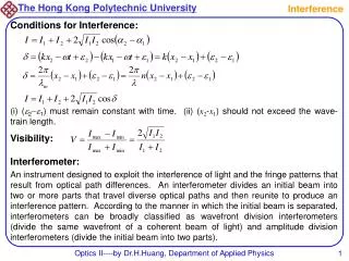
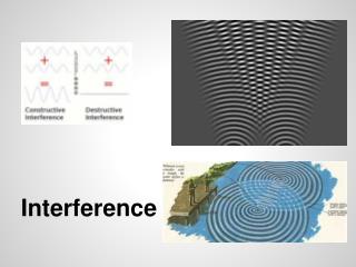
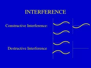
Interference Level II. The Wave Model of Light. The Wave Model of Light. Light is a transverse electromagnetic wave! It is composed of perpendicular electric and magnetic fields that propagate one another. Light waves can constructively and destructively interfere with one another.

Interference Level II
E N D
Presentation Transcript
The Wave Model of Light • Light is a transverse electromagnetic wave! • It is composed of perpendicular electric and magnetic fields that propagate one another. • Light waves can constructively and destructively interfere with one another. • Light waves obey v = λf • Light waves propagate according to Huygens’ Principle.
Crossed, oscillating electric and magnetic fields will propagate indefinitely and without loss of energy at speed c through a vacuum.
The Electromagnetic Spectrum! All of these frequencies of light travel at speed c in a vacuum (3 x 10⁸ m/s).
A mnemonic to help you remember the spectrum! (in order of increasing frequency) Radio Microwave Infrared Visible Ultraviolet X-ray Gamma Rattlesnakes May Inject Venom Upon eXtreme aGitation
Human eyes are only able to detect light of wavelength 480-720 nm. That is why this is called the visible range of the spectrum. The wavelength that we perceive as red is about 480 nm. The wavelength that we perceive as violet is about 720 nm. Different animals are able to detect different ranges of EM waves! The image on the right shows the ultraviolet light given off by a dandelion. Bees and other insects have eyes that are capable of detecting UV light!
Why are we able to detect 480 – 720 nm electromagnetic waves with our eyes? That is the peak range of wavelengths emitted by our Sun!!!
Quick Conceptual Whiteboard Review! What happens to the speed and the wavelength of light as it crosses the boundary in going from air into water? SpeedWavelength (A) Increases Remains the same (B) Remains the same Decreases (C) Remains the same Remains the same (D) Decreases Increases (E) Decreases Decreases
Frequency of a wave does not change upon entering a new medium! The frequency of an EM wave governs how much energy it carries. Frequency is a property of the wave, and is set once the wave is produced. Wave speed and wavelength will change inversely upon entering a new medium!
The Doppler Effect also applies to light! If a source of light is moving toward an observer, the light that the observer receives will have a higher frequency and shorter wavelength than would normally be received! This is called blueshift. (Light is shifted toward the blue end of the spectrum – higher frequency) If a source of light is moving away from an observer, the received light will have a lower frequency and longer wavelength than normal! This is called redshift. (Light is shifted toward the red end of the spectrum – lower frequency)
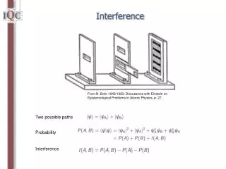
y θ d L When dsinθ = mλ, y will be a bright spot When dsinθ = (m-1/2)λ, y will be a dark spot tanθ = y/L
Whiteboard Warmup! A violet laser of wavelength 480 nm is incident upon two slits that are separated by a width of 0.5 mm. As a result, an interference pattern of bright and dark bands appears on the wall 4 m away. Determine the positions of the central bright band, first-order dark bands, and first-order bright bands produced on the wall. Draw and label this part of the interference pattern on your whiteboards.
A little proportional reasoning! What would happen to the interference pattern if you increased the distance between the slits? What would happen if you were to use ultraviolet light instead? Explain your reasoning for both cases!
Approximations for small theta If θ is sufficiently small (as it will be for the first few bright and dark bands), we can use the approximation that the light waves travel a distance of ≈ L to reach the screen ≈ L y d L θ This gives us the useful approximation
For small theta, We can use the approximation combined with dsinθ = mλ (bright band) dsinθ = (m – ½)λ (dark band) To obtain the simplified result for the positions of the bright and dark bands Bright bands (m = 0, 1, 2, 3…) Dark bands (m = 1, 2, 3…)
Bright bands (m = 0, 1, 2, 3…) Dark bands (m = 1, 2, 3…) This means that the second bright band would be twice as far from the center as the first bright band. The third bright band would be three times as far, etc. When θ is small, the bright bands will be evenly spaced.
What will the light intensity on the screen look like? Evenly spaced bright bands! (for small θ) m = 1 m = 1 m = 2 m = 2
Wave Model Whiteboard A green laser of wavelength 520 nm is incident upon two slits that are separated by a width of 0.3 mm. As a result, an interference pattern of bright and dark bands appears on the wall 7 m away. Determine the distance between the third-order bright bands on either side of the central bright band.
Interesting Side Note Two-source interference is commonly used in biology labs to measure the size of very small objects (bacteria, viruses, width of a hair, etc). Check out the picture above to see how it’s done!
Single Slit Interference • A single slit, if thin enough, will also produce an interference pattern! • Although the reason for this is somewhat complex, the heart of it lies in Huygens’ Principle. • The math for the single slit is the opposite to that for the double slit.
Single Slit Interference Since each point of the opening acts as a point source of light, a thin single slit will create an interference pattern. The main difference between the single and double-slit pattern is that in a single slit pattern, the central bright band will be very wide and bright, and the subsequent bright bands will be significantly less bright. Also known as Fraunhofer Diffraction
Equations for a Single Slit y θ w L When wsinθ = mλ, y will be a dark spot w is now the width of the single slit!
Single Slit Interference Whiteboard A red laser of wavelength 690 nm is incident upon a single slit that has a width of 0.1 mm. As a result, an interference pattern of bright and dark bands appears on the wall 4 m away. Determine the approximate width of the central bright band!