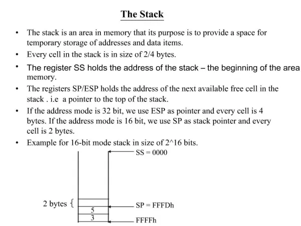
Download

1 / 21
210 likes | 217 Views
Designing For The NESDAC Stack. January 3, 2020. Outline. Architecture Common design requirements Examples Compromises Results The Future. Unregulated Power. Regulated Power. Serial Communications. Parallel Communications. General Purpose I/O. Expansion. Inter-module Bus.

E N D
Designing For The NESDAC Stack January 3, 2020
Outline • Architecture • Common design requirements • Examples • Compromises • Results • The Future
Unregulated Power Regulated Power Serial Communications Parallel Communications General Purpose I/O Expansion Inter-module Bus • Supports a variety of communication schemes • Has regulated and unregulated power supplies • Unused lines left undefined for future expansion
Module Form Factor • Custom battery holder defined module size as 1.25”x1.5” (based on batteries) • Board to board spacing of either 3.5 or 5 mm • Limit components to: • 3.5 mm tall on top • 1.5 mm tall on bottom • Size suitable to most applications 0.3” 0.6” 1.25” 1.5”
Connector Pin-outs • 2 x 20 pin connectors on each side of the module • 3.3V and VBatt, 3 pins each for current • 6 ground pins • I2C clock (SPI clock), I2C data (slave out), master out, slave enable, open-drain interrupt line • UART Rx and Tx • One 8-bit port (interruptible) • 13 more GPIO • Exact definition shown later
Connector Footprints • Pins pass straight through the board • P1 directly under J1, P2 under J2 • Cannot be plugged together incorrectly • May require two different footprints for top and bottom • J1, P2 are plugs • J2, P1 are sockets
MCU 3.3V Boost Converter B U S Local power mgt. Comms Level Translation MCU Powering the Stack • Provide battery power to each module over the bus • Regulate a low-current common voltage for communication standardization • Filter power locally (battery and 3.3v) to reduce inrush current spikes from propagating back over the bus • Microcontroller can monitor battery voltage • Use CR2’s or 2/3AA batteries • Available in several varieties (LiMNO2, LiSOCL2) • Helped to define the form factor shown earlier • Capable of high current as well as long life
Local Resource B U S Battery Power Local Power Management +Vbatt +Vdd +3.3V MSP430 MCU I2C SPI/I2C Level Converter I2C SPI SPI 8-bit I/O 8-bit I/O 8-bit Level Converter Local Power 3.3V Power Communicating over the Bus • Serial communication • I2C or SPI • Several GPIO lines included • Room for expansion • Use a 3.3V reference and level translators to standardize communication • 3.3V boost converter required on power supply • Low output current, very low Iq converters are available • I2C requires special translators
Programming Modules • Separate programming header on each module • Adapter board connects to header • Allows in-circuit programming and debugging of modules • Also has RS-232 interface • Programming requires higher voltages • Plugging in the programming adapter bypasses local power regulation Programming Adapter
Debugging the Stack • “Debug board” breaks out inter-module bus • Allows boards to be cabled together flat on a table for easy access • Bus can be monitored easily • Each module can be programmed and debugged individually and simultaneously. Debug board
General Module Design • Local power regulation • Local power filtering and decoupling • Serial communication level converters • GPIO level converters Resource B U S Local Power Supply Vdd +Vbatt Micro- controller I2C, Vdd SPI/I2C Level Converter I2C, 3.3V SPI, Vdd SPI, 3.3V 8-bit I/O, Vdd 8-bit I/O, 3.3V 8-bit Level Converter
Reality • Communication had many issues • Level converters did not work as advertised • I2C is too slow for many applications • I2C is flawed in first generation MSP430 devices • Connectors are a weak link • Power • Higher operating voltage required by mC • Programming needs 2.8V • Higher clock speeds require higher voltages • External power switch required by some applications • Power filtering is an absolute must on every module
Serial Communication • SPI • Multiplexed I2C lines with SPI • Applications can use either, but not both • Faster, up to ½ processor clock • Slaves must request service from the master • Requires interruptible GPIO lines (1 per slave) • Slaves require individual enable lines or an addressing scheme in the packet structure • Disadvantages: • No built-in acknowledgement like I2C • No hardware addressing, start/stop, etc. • Not multi-master • Uses many bus lines • Converted to 3.3V with FETs • Wastes some energy due to pull-ups
Serial Protocol • Flexible packet structure: • Destination (2 bytes) • Source (2 bytes) • Message ID (1 byte) • Command (1 byte) • Payload length (2 bytes) • Payload (N bytes) • Checksum (1 byte) • SPI allows use of DMA for transfers (2Mbit/s) • DMA can only execute a specified number of times • Variable length packets are problematic • Packets are temporarily filled out to a preset length
I2C/SPI Level Translation • FETs allow open-drain operation. • 3.3V pull-up resistors • Footprints on every board • Loaded in only one location (generally the power supply)
MCU 1 B U S 8-bit I/O, Vdd 8-bit Level Converter Won’t talk! 8-bit I/O, 3.3V 8-bit Level Converter 8-bit I/O, 3.3V 8-bit I/O, Vdd MCU 2 GPIO Problems • Bidirectional Maxim level converters don’t work • One converter can’t drive another • Bypassed them “for now” • Can cause problems • Have to make sure voltages are compatible • Creates floating lines • Reduces isolation • Still waiting for a better part
Present Connector Pinout Includes I2C/SPI, interrupt line, UART, 1 slave enable, GPIO, power. SPI: SIMO on I2C_SDA, SOMI on GPIO6, UCLK on I2C_SCL
Local Module Power B U S • If higher clock speeds are necessary: • Load power supply to send 3.3V instead of VBatt • Run mC off VBatt (3.3V) • Jumpers (resistors) can be used to allow either VBatt or 3.3V as power • Always filter and decouple power locally! • Analog circuits • DO NOT connect analog to VBatt or 3.3V directly. • Regulate power locally and filter! Digital Electronics +3.3V LC Filter Jumper +Vbatt Filter Analog Electronics Analog Power
Power Circuits Local power regulation with programming bypass. DBG* is pulled low when the programming adapter is plugged in. Load R11 with 0 ohm to force bypass. Selectable power source with filter.
5mm 38mm 10mm 18mm 5mm 7mm 23mm 20mm 32mm 32mm 18mm 38mm 5mm 7mm 10mm 5mm