Download
1 / 70
700 likes | 868 Views
This study investigates light scattering phenomena associated with aggregates and closely packed layers of particles, particularly focusing on Saturn's F Ring. We explore how light scattering occurs in nature, examining both diffuse particle layers and compact particle layers. Using data from the Cassini VIMS mission, we propose new models for understanding particle composition, scattering mechanisms, and the implications for future work in planetary science. Our findings highlight the importance of particle aggregates in interpreting scattering behavior and their potential roles in planetary formation.

E N D
Scattering by aggregates and layers of closely packed particlesSanaz VahidiniaJeffrey Cuzzi, Bruce Draine, Frank Bridges
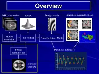
Overview • Introduction • Light scattering in nature • Saturn’s F ring aggregates • Scattering from diffuse particle layer • Independent scattering • Cassini VIMS data, modeling, and results • Regolith scattering • Scattering from compact particle layers • Interference effects • motivation, current models, our new model • results • Future work
1. diffuse layer 2. diffuse aggregate layer 3. compact layer
Part 1: Studies of Saturn’s F ring particles As aggregates
Cassini’s Telescopes RSS, Radar MIMI (neutrons ! ) ISS (vis, near-IR mapping spectrometer) (WA, NA cameras) RPWS (AM, FM) CIRS UVIS Ultraviolet imaging spectrograph (occultations, mapping) Composite infrared Spectrometer (thermal emission)
D C B C D A F ISS approach color composite
what kind of particles could the F ring particles be? solid, porous, or aggregates or ??? aggregate DDA porous homogeneous particle Mie theory + EMT solid homogeneous particle Mie theory
solid carbon particles vs. solid ice particles solid ice particles vs. data
what kind of particles could the F ring particles be? solid, porous, or aggregates or ??? aggregate DDA porous homogeneous particle Mie theory + EMT solid homogeneous particle Mie theory
Discrete Dipole Approximation • Model each dielectric grain with an array of N polarizable dipoles with polarizability . • Assign polarizability such that the dipole lattice exhibits the macroscopic dielectric constant of the material. • Each dipole is driven by an incident field and the field of all other oscillators in the lattice. • The steady state polarization or field in the material is found by an iterative method. • Pj = Ej = ·(Ei + k2(Pj * G) ) • - 1 = 4N/(1- 4N/3) • 2m(d / ) < 1/2 DDA Constraint
extinction efficiency (Qext) = Qa + Qs = ext / r2 albedo (w) = Qs / Qext I / F = Qext * w * p * n * r2 phase (p) = phase function
Part 1 conclusions: • F ring particles are not well modeled by uniform density • spheres, even if arbitrary density is allowed • Aggregates fit better and allow fit to overall shape of spectral • Forward scattering I/F AND depth of single observed absorption • feature • Aggregates are more effective scatterers per unit mass; • toy model explains why (interfaces) • Single abs feature has been explained as Christiansen • frequency and allows us to discriminate between crystalline • and amorphous ice • F ring aggregate particles have a moderately narrow • size distribution
Part 2: Regolith radiative transfer: A new approach with applications To many granular surfaces
1. diffuse layer 2. diffuse aggregate layer 3. compact layer
Saturn’s entire B ring HST IRTF model R wavelength (microns) 98% water ice, 2% carbon, 1% tholins F. Poulet et al. (2003) Groundbased reflectance spectrum: water ice bands and reddish material Certain regions get more “polluted” wavelength, microns
Grains are good absorbers of short Grains start to scatter radiation in this region 1.0 B A C • Roll off is the transition region between good absorbers and perfect reflectors. • This region is difficult to model due to closely packed grains and grain sizes comparable to . Ring particles become good scatterers in the microwave region 0.5 1000 10 100 Wavelength (m) Spilker et al.(2005) Ring emissivities of the A,B, and C rings as a function of wavelength.
Thermal IR and microwave: change from emitting to scattering behavior Most ring particles are wavelength size (cm-m) and Composed almost entirely (>90%) of water ice; Transition region (100 - few mm) poorly characterized Data tabulated in Esposito et al 984
Review of current RRT modelsand sample calculation of Quartz emissivity using current model…motivation fordevelopment of our model
Equation of Transfer Ir I0 0 0 0 It P = particle phase function, which gives the angular distribution and polarization of scattered light for any polarization of incident radiation. g = cos P11 d/4, anisotropy parameter characterizing the shape of the phase function. w = single scattering albedo. Defined as the fraction scattered, of the total energy removed from the incident beam. Methods of solving the Transfer Equation for plane parallel layers
Current RRT models Some of the current transfer solutions can be summarized in two parts Calculate grain Albedo (w) using: Mie theory … Spherical particles, well separated (Conel, Hansen,..) Ray optics … Particles large compared to wavelength, allows for irregular particles (Hapke) Multiple scattering calculation for layer: Isotropic scattering in a homogenous semi infinite layer can be solved by Chandrasekhar's semi-analytic H-function. The H function is a nonlinear integral equation used to numerically solve the reflection from an infinite layer. Anisotropic scattering can be solved using van de Hulst’s Similarity relations. This method approximates complex phase functions in terms of solutions for simpler phase functions (specifically isotropic phase functions). (Cuzzi & Estrada, Shkuratov, Conel…) The Doubling/Adding method is a numerical approach where the overall transfer properties of one layer is calculated by equating the emergent radiation from an arbitrary layer to the incident radiation upon the layer in question. (Hansen, Eddington…)
Emissivity of a layer of particles Bc=Black body radiation intensity Bc Black body surface at Tc Bc • Black body radiation gets absorbed, scattered, and re-emitted by the layer. • The radiation contributions from the layer can be broken up into the following: 1) Direct transmission of black body radiation 2) Diffusely scattered radiation transmitted through the layer . through the layer. 3) Diffusely scattered radiation reflected by the layer. 4) Emitted radiation from the layer. Conservation of Energy ~
Outline of Mie/similarity calculation for quartz emissivity data A = S(, ) d do = ring particle spherical albedo using van de Hulst’s similarity parameter S = [(1 - w) / (1 - w•g)]1/2 A = (1- S)(1-0.139 S) /(1+1.175 S) Emissivity = 1 - A
Mie scattering for grain albedo(w) and g • Similarity transformation for particle (or integrated) albedo • Integrated emissivity = 1 - Integrated Albedo • Data courtesy J. Michalski
Current models don’t match the emissivity data. Current models make various simplifying assumptions and do not account for close packing, interference effects, and irregular particles. We need to develop an RRT model that takes all these effects into account
Discrete Dipole Approximation • Model dielectric grain with an array of N polarizable dipoles with polarizability . • Assign polarizability such that the dipole lattice exhibits the macroscopic dielectric constant of the material. • Each dipole is driven by an incident field and the field of all other oscillators in the lattice. • The steady state polarization or field in the material is found by an iterative method. • Pj = Ej = ·(Ei + k2(Pj * G) ) • - 1 = 4N/(1- 4N/3) • 2m(d / ) < 1/2 DDA Constraint
Layer radiative transfer s T {s + T} ()
Scattered field on a plane in the near field (either reflection or transmission) Note periodic boundary conditions x y FFT E(x,y) = k2(Pj * G) E(, )
Angular Spectrum G = Green’s function (J. D. Jackson) 2-D vector field Fourier transform vector field to k-space k-space power spectrum
x Angular distribution of scattered intensity evanescent waves occur when: z y Resolution Specifications
Dielectric slab test • Simulate a homogeneous dielectric layer with DDA-PBC code. Calculate reflection and transmission from the layer with the near field method. • Compare R and T with Fresnel coefficients. • Granular runs • Run a granular layer with various porosities. Examine transmission and reflection as a function of particle packing.
Io R T
Specular beam in k-space Specular reflection: reflected beam is localized in frequency space at three emission angles corresponding to three incident zenith angles 20o, 40o, and 60o.
Optical depth studies of granular layers z • Calculate Q from the optical depth and compare with • current mie models • Use optical depth for the adding code