Download
1 / 36
370 likes | 632 Views
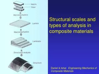
Structural Materials for Fusion Power Plants Part II: Multi-scale Modelling Radiation Effects. Presented by J. L. Boutard 1 1 EFDA CSU-Garching. Coordinated by S. Dudarev (UKAEA) Helsinki University: K. Nordlund, N. Juslin, C. Björkas VTT Finland: S. Tähtinen (VTT)

E N D
Structural Materials for Fusion Power Plants Part II: Multi-scale Modelling Radiation Effects Presented by J. L. Boutard 1 1 EFDA CSU-Garching Stefan Kolmsperger Feb 2006 PowerPointTemplate for EFDA
Coordinated by S. Dudarev (UKAEA) Helsinki University: K. Nordlund, N. Juslin, C. Björkas VTT Finland: S. Tähtinen (VTT) Uppsala University: J. Wallenius, P. Olsson Riso National Lab: B.Singh UKAEA: S. Dudarev, D. Nguyen Manh, M. Lavrentiev SCK.CEN Mol: L. Malerba, D. Terentyev, M. Matijasevic, A. Almazouzi, P. Jaquet FZK: A. Moslang, M. Rieth, M. Klimenkov TU Bratislava : V. Slugen CRPP: R. Schaeublin, G. Lucas, A. Ramar CEA: F. Willaime, C. C. Fu, A. Barbu, L. Ventelon University Polytechnical Madrid: M. Perlado University Alicante: M. J. Caturla, C. Ortiz TU Karlsruhe: D. Weygand, M. Mrovec Fusion Euratom Programme:Modelling Radiation Effects in EUROFER Fusion or Fission National Programmes: • UK: P. Klaver Uni Belfast), S. Roberts & M. Jenkins (Uni Oxford) • France: D. Rodney, J. Chaussidon Stefan Kolmsperger Feb 2006 PowerPointTemplate for EFDA
Radiation Effects Modelling (1) Objectives of the EU Programme • To study the radiation effects in the EUROFER RAFM steel • In the range of temperatures from RT to 550 0C • Up to high dose ~100dpa • In the presence of high concentrations of transmutation impurities (i.e. H, He) • To Develop modelling tools and database capable of: • Correlation of results from: • The present fission reactors & spallation sources • The future intense fusion neutron source IFMIF • Extrapolation to high fluences and He & H contents of fusion reactors • To experimentally validate the models at the relevant scale M. Victoria, G. Martin and B. Singh, The Role of the Modelling Radiation Effects in metals in the EU Fusion Materials Long Term Program (2001) Stefan Kolmsperger Feb 2006 PowerPointTemplate for EFDA
Outline • Radiation induced defects and He accumulation in Fe-(C) • Phase Stability of Fe-Cr system, based on DFT • Dynamical Properties of Dislocations in Fe and Fe-He • Concluding remarks Stefan Kolmsperger Feb 2006 PowerPointTemplate for EFDA
Modelling Radiation-Induced Point Defect and He accumulation Stefan Kolmsperger Feb 2006 PowerPointTemplate for EFDA
Long Term Prediction Primary Damage Short Term prediction Displacement Cascades Micro -- ShortTerm Recovery Diffusion Ballistic Phase Thermalisation structure Lifetime of components 0 10-13 s 10-13 10-11s 10-8 s - 15 - 8 10 s 10 s 10 -11 s Lifetime of Components Molecular Dynamics Rate Theory Atomic Kinetic Monte Carlo Monte Carlo on Objects Molecular Dynamics Monte Carlo on Events Radiation Modified MicrostructureScale and tools for Multi-scale Modelling No long range strain Only effect of dislocations is their bias and action as sink. Stefan Kolmsperger Feb 2006 PowerPointTemplate for EFDA
1NN Criterion 3NN Criterion 2NN Criterion Molecular Dynamics SimulationProduction Efficiency & Fraction of Clustered Defects L. Malerba, J. Nucl. Mater. 351 (2006) 28-38 • Important scattered in clustered defect fraction makes these MD simulation useless as the first block of radiation effects modelling • No convincing argument except • The inter-atomic potentials were predicting the <111> SIA as stable configuration in a-Fe Stefan Kolmsperger Feb 2006 PowerPointTemplate for EFDA
V: T<6K Nb: T<6K Ta: T<6K Cr: T=40K Mo: T=35K W: T=27K <111> Em ~a few 0.01eV T e- e- e- e- e- Resistivity (r) Stage I <110> Em ~0.3-0.4 eV Fe: T=140K T -dr/dT T recovery stages Indirect Experimental Knowledge of Point Defect Energetics:Damage Resistivity Recovery in Pure Metals Electron irradiation Isochronal Annealing Damage Recovery: Stage I H. Schultz, Atomic Defects in Metals, Landolt-Börnstein New Series, Group III, vol. 25, Springer-Verlag Berlin, 1991, p. 115. Stefan Kolmsperger Feb 2006 PowerPointTemplate for EFDA
MagnetisationFe: <110> + 2.5 µB Magnetic Fe <110> Non Magnetic <111> -0.7 µB Self Interstitial Atoms in bcc Transition Metals: DFT Calculations D. Nguyen-Manh, A. P.Horsfield and S. L. Dudarev Phys. Rev. B73 (2006) 20101. Stefan Kolmsperger Feb 2006 PowerPointTemplate for EFDA
Grey area: simulation with previous potentials Grey area: simulation with previous potentials Large scatter Large scatter Number of Frenkel pairs Strong reduction in the scatter Interstitial clustered fraction Still some scatter to understand Empirical Potential based on ab initioMolecular Dynamics simulation of cascades in a-Fe • Three a-Fe Semi-Empirical potentials developed in 2006 • Based on different functional forms and physical assumptions • Reproducing ab-initio SIA energetics: <110> SIA is the stable configuration in a-Fe K. Nordlund (TEKES) to presented at ICFRM-13 Nice December 2007 Stefan Kolmsperger Feb 2006 PowerPointTemplate for EFDA
III 278K Exp.: ID2 107.5K IE 144K II 185K Resistivity Concentration Interstitial Migration Vacancy Migration Di-Interstitial Migration Correlated Pairs Em (V)= 0.67 eV Em (I)= 0.34 eV Ab initio Em (I2)= 0.42 eV Isochronal Thermal Recovery of Radiation damage in a-Fe Ab initio based Event Kinetic Monte-Carlo S. Takaki , J. Fuss, H. Kugler, U. Dedek and H. Shultz, Radiat. Effects 79 (1983) 87-122 C.C. Fu, J. Dalla Torre, F. Willaime, J.L. Bocquet, A. Barbu in Nature Materials 4, 68 (2005) Stefan Kolmsperger Feb 2006 PowerPointTemplate for EFDA
He & point defects energetics based on DFT: Solution Energy Substitution: HeV Tetrahedral: He Octahedral: He C. C. Fu and F. Willaime Phys. Rev B72 (2005) 064117. 23 MeV 4He2+:Jülich Compact Cyclotron • Microstructure after Implantation: • Frenkel Pairs • He in substitution: • He is Created as interstitial but Em=0.06 eV so that migration is fast even at room temperature and reaction with vacancies easy Stefan Kolmsperger Feb 2006 PowerPointTemplate for EFDA
Binding Energy: • (a) with • (b)with (a) (b) He and point defect energetics based on DFT: (2) Diffusion and Clustering • Interstitial He Diffusion • Dissociative Diffusion Mechanism • Kick-out mechanism • Vacancy mechanism by migration of HeV2 Complex C. C. Fu and F. Willaime Phys. Rev B72 (2005) 064117. • Mobile Defects: V, SIA & di-SIA C.C. Fu and F. Willaime, Phys. Rev. B72, (2005) 064117. C.C. Fu et al. Nature Materials 4, 68 (2005) Stefan Kolmsperger Feb 2006 PowerPointTemplate for EFDA
Rate Theory Kinetic ModelingHe-desorption: (1) Role of Carbon C. J. Ortiz, M. J. Caturla, C. C. Fu and F. Willaime Phys. Rev. B75 (2007) 100102. Based on Ab initio energetics: Modelling does not reproduce the He –desorption (*) Ef (V) = 1.6 eV instead of 2.0eV (DFT) Em (V) = 1.1 eV instead of 0.67eV (DFT) And Eb(V-Hen-Vm-1) accordingly as: Eb(V-HenVm-1)=Ef(V)+Ef(HenVm-1)-Ef(HenVm) (*) R. Vassen, H. Trinkaus, P. Jung Phys. Rev. B44 (1991) 4206. The fitted migration energy for vacancy suggests that vacancies are interacting with trapping impurities. Interstitial carbons might be such trapping centers Stefan Kolmsperger Feb 2006 PowerPointTemplate for EFDA
Rate Theory Kinetic ModelingHe-desorption: (2) Towards model-designed experiments Flux of interstitial Hedue to: 1. Kick-Out (KO) mechanism: HeV + I -> He 2. Frank-Turnbull (FT) mechanism HeV -> V + He 3.Dissociation of V from clusters: HenVm -> He(n-1)Vm + Hei Next Step: Develop an ab initio parameterized kinetic Monte Carlo for Fe-C-He : Design desorption experiments to separately quantify the He-diffusion mechanisms Stefan Kolmsperger Feb 2006 PowerPointTemplate for EFDA
Phase Stability based on DFT calculated Enthalpy of Atomic Configurations Stefan Kolmsperger Feb 2006 PowerPointTemplate for EFDA
0.456, 1105 K 0.192 0.846 785 K CALPHAD Fe-Cr Phase Diagram The important region for Fusion is the low temperature Fe-rich domain where Experiments are difficult since low temperature means low time to reach equilibrium There is phase instability at lower temperature range Stefan Kolmsperger Feb 2006 PowerPointTemplate for EFDA
Ab initio EMTO CPA CALPHAD M. Yu. Lavrentyev Phys. Rev. B 75, (2007) 014208 P. Olsson et al. J. Nucl. Mater. 321(2003) 84-90 Non-symmetric Fe-Cr Formation Enthalpy • Fe-Cr System: DFT Calculation of the Formation Enthalpy Random Solid Solution described by Coherent Potential Approximation Minimum value obtained by Exchange Monte Carlo on a ab initio set of configuration enthalpies • Consequences of the sign change in the Fe rich domain at 0K: Cr is soluble in Fe &above ~6%Cr the system unmix into Cr and Fe- ~6%Cr alloy • Present CALPHAD Fe-Cr phase diagram does not reproduce this behaviour as the Formation Enthalpy does not change sign: • with Complete Solid solution Miscibility Gap Stefan Kolmsperger Feb 2006 PowerPointTemplate for EFDA
Phase Stability of Fe-Cr:Essential Role of Magnetism • Fe: Large Ferromagnetic Ordering Energy ~0.5 eV/atom. Stabilisation of the ferromagnetic bcc crystalline structure versus: • NM fcc structure: high temperature crystalline structure of Fe • NM hcp structure: structure of the isovalent 4d (Ru) and 5d (Os) G. Liu, D. Nguyen-Manh, B.G. Liu and D. G. Pettifor Phys. Rev. B71, (2005)174115 • Cr: spin density wave or anti-ferromagnetic ground state are matter of debate, with very small energy difference. Metallic impurities (Mn) are reported to stabilize the Anti-Ferromagnetic Magnetic (AFM) order: • The AFM-ordering energy is weak ~ 0.014 eV/atom. T. P. C. Klave, R. Drautz and M. W. Finnis Phys. Rev. B74 (2006) 094435. R. Hafner, D. Spisák, R. lorentz and J,. Hafner J. Phys.: Condens. Matter 13 (2001) L239-L247. Stefan Kolmsperger Feb 2006 PowerPointTemplate for EFDA
(b) (a) Magnetic Non Magnetic Cr-Solution & Cr-Cr interaction in the Fe-Cr System • Solution energy of Cr in a-Fe is slightly negative: DE sol~ - 3 meV/atom (a) For a system with two Cr the highest energy is when both Cr are Nearest Neighbours (NN) and the system energy decreases monotonically with Cr separation by at least 0.3 eV: Such an energetics maximize Cr-Cr separations favours ordering and the existence of solid solution and ordering • The nearest neighbour Cr-Cr repulsion is due to magnetism as it has completely changed in the Non Magnetic (NM) case. Magnetic frustration is governing the solubility of Cr in Fe in the Fe-rich domain The longer range repulsion from 2nd to 6th NN is very similar in the magnetic and NM should have another origin than magnetism. First NN Cr Magnetic Frustration T. P. C. Klaver, R. Drautz and M. W. Finnis Phys. Rev. B74 (2006) 094435. Stefan Kolmsperger Feb 2006 PowerPointTemplate for EFDA
(a) (b) Squares are not well mixed systems where Fe interact mostly with Fe and Cr with Cr Square are systems with no NN magnetic frustration Long Range Many-Body (LRMB) Interaction • The Cr-Cr interaction energy is always NEGATIVE, it cannot explain the positive Mixing heat above ~10% Cr • For the equi-molar system Fe0.5Cr0.5the B2 structure allows solving the magnetic frustration and yet the formation enthalpy is positive • LRMB Interaction • Image forces due to too small cells • High formation Heat of the most random configuration Magnetic Frustration T. P. C. Klaver et al. Phys. Rev. B74 (2006) 094435. Stefan Kolmsperger Feb 2006 PowerPointTemplate for EFDA
The Mixing enthalpy calculated ab initio can be mapped exactly onto Ising-like Hamiltonian: Where : are an infinite set of effective interaction independent of the atom occupying the site I, j or k is equal to 1 if the site i is occupied by a Fe atom is equal to -1 if the site I is occupied by a Cr atom CE Prediction Phase Stability in the Fe-Cr systm (MCX &CE) (1) Cluster Expansion (CE) based on DFT calculation With 12 clusters and CE J coefficients independent of the occupancy of the crystalline site: DFT formation enthalpies (4x4x4 supercell) of 74 atomic configurations are reproduced with a predictive error ~7 meV M. Yu. Lavrentiev, R. Drautz, D. Nguyen-Manh, T.P.C. Klaverand S.L. Dudarev Phys. Rev.B75 (2007) 014208 Stefan Kolmsperger Feb 2006 PowerPointTemplate for EFDA
Phase Stability in the Fe-Cr system (MCX & CE) (2) Exchange Monte Carlo (MCX) based on Cluster Expansion (CE) • Exchange Monte Carlo (MCX) allows: • sampling the various configurations in system where configuration disorder is important like in Fe-Cr and • calculating easily enthalpies and variation of Gibbs free energy at thermal equilibrium • A random exchange between the different atoms of a pair is proposed. The decision whether to accept or to reject the move is made according the Metropolis scheme: • If the induced energy change DU is negative the change is accepted, • if DU is positive the exchange is accepted with if the probability r is a random figure between 0 and 1 • System handled can have a few hundreds of thousands of atoms: • 40x40x40 bcc units cells (128,000 atoms), 60x60x60 unit cells 432,000 atoms or 80x80x80 unit cells (1,024,000 atoms) • with for each run a total of ~10 8 exchanges • Mixing enthalpy versus T and Cr content • Chemical potentials in the semi-grand canonical ensemble • Clustering and Ordering behaviour Stefan Kolmsperger Feb 2006 PowerPointTemplate for EFDA
No clustering One large cluster 10 %Cr, 800K 10 %Cr, 0K 0 K 0 K Unmixing into Fe-6.25%Cr and Cr phase Solid Solution Fe-Cr Clustering Clustering Ordered Compound Fe-6.25%Cr 8 Cr atoms in the 4x4x4 super-cell (128 atoms) Cr are not closer than 6th NN 11 %Cr, 800K 10 %Cr, 200 K Phase stability in the Fe-Cr system (MCX & CE)(3) Enthalpy of mixing and clustering M. Yu. Lavrentiev et al.Phys. Rev.B75 (2007) 014208 Stefan Kolmsperger Feb 2006 PowerPointTemplate for EFDA
Simulation CE+MCX Simulation 2b-EP+kMC Comparison with experimental data:(1) Short Range Order inversion in Fe-Cr • Short Range Order • Described by the Warren-Cowley parameter • Is the conditional probability of finding Fe atom in the Nth coordination sphere of a Cr atom • If no Short Range Ordering: therefore • If Cr clustering: therefore • If Cr ordering: therefore • Diffuse neutron scattering & electrical resistivity measurements showed that the SRO parameter change sign at 705 K around 10% Cr (*) P.Olsson, K. Nordlund and al. M. Yu. Lavrentiev et al.Phys. Rev.B75 (2007) 014208 (*) I. Mirebeau, M. Hennion and G. Parette Phys. Rev. Lett. 53 (1983) 2351. Stefan Kolmsperger Feb 2006 PowerPointTemplate for EFDA
Comparison with experimental data:(2) Closure of the miscibility gap Fe-Cr Phase Diagram obtained with CD-EP Only the Magnetic Phases are shown By courtesy of A. Caro [a] A. Caro et al., MRS Fall 2006 [b] TW5-TTMS- 007. Final Report Dec. 2006. K. Nordlund , N. Juslin, C. Björkas, L. Malerba, D. Terentyev [c] M. Yu. Lavrentiev et al.Phys. Rev. B75 (2007) 014208. Stefan Kolmsperger Feb 2006 PowerPointTemplate for EFDA
Modelling Dynamical Properties of Dislocations Stefan Kolmsperger Feb 2006 PowerPointTemplate for EFDA
Multiscale modeling of Dislocation Coupling with experiments Experiments Dislocation Dynamics • Perfect dislocations • T = 0 K • = 0 Molecular dynamics Empirical potentials Ab initioElectronic structure calculations • Dislocations with kinks • T 0 K • 0 102 atoms 106 atoms Time 100 ps 1 ps System size After F. Willaime SRMP CEA/Saclay Stefan Kolmsperger Feb 2006 PowerPointTemplate for EFDA
Dislocations in bcc metals Elasticity Theory (1) Screw dislocation: is parallel to the dislocation line • Geometry and Crystallography • The dislocation line separates two parts of the crystal (i) one has glided (ii) the other has not. • The glide is defined in direction and value by the Bürgers vector equal to a/2<111> • can belong two three planes (110), (120) and (231), which are a priori possible glide planes b b b b Stefan Kolmsperger Feb 2006 PowerPointTemplate for EFDA
b d A B C Dislocations in bcc metalsElasticity Theory (2) • Peierls Barrier or Peierls Nabarro stress • To move a dislocation as a whole from the equilibrium A to the next one C to overcome an enthalpy of activation per unit line DW or a critical stress sPN characteristic of the position B The a/2 {110} glide system is the most favourable in agreement with experimental observation in bcc Fe [a] [a] W.A Spitzig and S. A. Keh, Acta Metall. 18 (1970)611 Stefan Kolmsperger Feb 2006 PowerPointTemplate for EFDA
b Degenerate core Non-degenerate core Core structure of <111> screw dislocations in bcc metals Lisa Ventelon & F. Willaime Invited talk ICFRM-13 Dec2007 Nice (F) • Pair potentials (Vitek, ‘70) • For bcc Fe: • Dudarev-Derlet (J. Phys. Cond. Mat. 2005) • Ackland (Phil. Mag.1997) • DFT in V, Ta, Nb, Cr, Mo, W and Fe • Mendelev potential in Fe (Phil. Mag. 2003) Molecular Simulation of Fe screw dislocation with degenerate core : a/2 {112} is the glide system at odds with experimental results J. Marian, W. Cai and V. Bulatov Nature Materials, Vol 3, March 2004, 158-163 Stefan Kolmsperger Feb 2006 PowerPointTemplate for EFDA
Non-degenerate core: MD & SIESTA Unit Cell Outer layer fixed to elastic displacement field with Periodic Boundary Conditions with Periodic Boundary Conditions Unit cell Screw Dislocation in bcc Fe(3) DFT calculation of Peierls Barrier Lisa Ventelon & F. Willaime Invited talk ICFRM-13 Dec2007 Nice (F) • Energy Barrier of a Screw Dislocation calculated ab initio with SIESTA and via MD with the Mendelev Empirical Potential [M. I. Mendelev et al. Phil. Mag.83 (2003) 3977] In agreement with other DFT calculations on bcc Fe by: S. L. Frederiksen and K.W. Jacobsen Phil. Mag. 83 (2003)365. • Dipole Method as rationalized by Cai & Bulatov • Cluster Method similar to Woodward et al. Stefan Kolmsperger Feb 2006 PowerPointTemplate for EFDA
Non-degenerate core: Degenerate core Critical Issues in MD Simulation of Dynamics Properties of Screw Dislocations in bcc Fe (1) • Selection of a correct potential: • Non-degenerated core structure required to reproduce the glide along (110) plane observed experimentally • Empirical potential predicting degenerate cores predicts glide along (112) [a] not observed experimentally • Kink pair formation energy is also an very important parameter for a correct prediction of the DBTT [b] [a] J. Marian, W. Cai and V. Bulatov Nature Materials, Vol 3, March 2004, 158-163 [b] J. Chaussidon, M. Fivel and D. Rodney Acta Mater. 54 (2006)3407-3416 Stefan Kolmsperger Feb 2006 PowerPointTemplate for EFDA
40 nm Dudarev-Derlet “Magnetic” Dynamical Properties of Dislocation:MD simulation of Hardening induced by He, and He-V-Clusters • Molecular Dynamic Simulation • Strain Controlled : 3.107 s-1 (60 m/s) • T: 10, 100, 200, 300, 500, 700 K • Simulation cell: 14 nm x 20nm x 20 nm • Obstacle forces: 2nm void • Obstacle strength ranking • He atom: negligible • Void : strong obstacle • He-V cluster: • Similar to voids: He/V<5 • Stronger than void: He/V>5 Increasing shear Robin Schaeublin et al. CRRP-EPFL (CH) Stefan Kolmsperger Feb 2006 PowerPointTemplate for EFDA
Concluding Remarks • DFT Calculations of : • atomic configuration, • activation energies of diffusion • Are forming a sound basis for modelling for phase diagram and kinetics evolution of materials • DFT based modelling of model-steel Fe-Cr-C is certainly at hand in the 5-10 forthcoming years. • For plasticity the recent progress of : • Dislocation Dynamics and • DFT calculation of core • MD simulation of dynamical properties of isolated dislocations • Should also give sound basis for plasticity predictions • Need for a strong interaction with experiment at the relevant scale and a strategy to • Take into account the increasing complexity from pure Fe to Fe-Cr-C model steel & actual steel • Use complementary experimental techniques Stefan Kolmsperger Feb 2006 PowerPointTemplate for EFDA
Thank you for your Attention Stefan Kolmsperger Feb 2006 PowerPointTemplate for EFDA