Download
1 / 22
240 likes | 443 Views
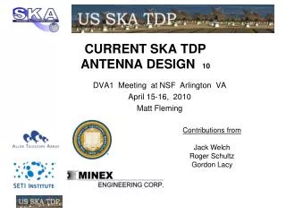
High Performance Low-Cost Composite Antenna Reflectors for the SKA. Gordon Lacy HIA/NRC April 2010. DOMINION RADIO ASTROPHYSICAL OBSERVATORY Herzberg Institute of Astrophysics Penticton BC. Why are Composites Interesting for the SKA?.

E N D
High Performance Low-Cost Composite Antenna Reflectors for the SKA Gordon Lacy HIA/NRC April 2010 DOMINION RADIO ASTROPHYSICAL OBSERVATORYHerzberg Institute of Astrophysics Penticton BC
Why are Composites Interesting for the SKA? • Composites offer a molded solution that lends itself to mass production. • Repeatable and accurate surface, high volume, low labour. • The Vacuum Infusion Process (VIP) allows molding the reflector in a single piece. • Low to zero assembly labour, zero panel adjustment labour. • Fiber Reinforced Plastics (FRP) can be tailored to have very high thermal stability (near zero thermal expansion), very high strength and stiffness, and be cost effective.
Why are Composites Interesting for the SKA? • FRP materials can have the highest possible stiffness-to-weight ratio, and this is one of the key structural requirement for radio reflector design. • Composite materials can easily be optimized for a specific application • materials suppliers are willing to participate in development with large enough orders
Composite Telescope Development at DRAO Composite radio telescope R&D, design, and fabrication has been ongoing at DRAO since 2006 Initial work included: • Embedded RF reflective layer testing (ongoing) • Materials Structural testing • Materials Process testing • Paint and coatings tests • Other Contracted R&D
Materials RF Testing Date Panel 11-Oct-06 04-Dec-06 17-Apr-07 22-May-07 Cu (mean) 0.0816 0.0840 0.0912 .0804 P 18 0.0946 P 17B 0.0947 P 19 0.1001 Al (mean) 0.1268 0.1298 0.1353 .1235 Al Ref 0A 0.1274 Al Ref 1 0.1295 Al Ref 0B 0.1312 Gal Steel 0.1495 Brass (mean) 0.1522 P 11 (mean) 0.2289 0.3186 P118 (mean) 0.2629 P111 (mean) 0.2890 P1B (mean) 0.2996 P3B (mean) 0.3078 P 22 0.4418 P 20 0.4930 0.3689 P 10 (mean) 0.5051 0.5992 P 4 (mean) 2.1085 P 21 2.1248 P5 (mean) 2.4329 P 3 (mean) 2.4638 P 1 (mean) 2.7026 Steel 3.8801 P 16 7.6064 P 6 17.7570 9 19.1130 Noise Temperature Measurement Results: Copper ~0.08 K Aluminum ~0.13 K Composite ~0.25 K Steel ~3.88 K
Mk1: Built Summer 2007 Mk1: 10m Centerfed Symmetric reflector • Built as proof of concept: • That a large composite reflector could be molded in a single piece • That the Vacuum Infusion Process was feasible for such a part • That the dish surface would retain its shape after molding
Mk1 Surface Accuracy • Shown are the Surface deviations from a best fit parabola and a comparison between dish surface measurements taken with a laser tracker and those taken using radio holography. • Maximum deviations are +4mm (red), -3mm (blue). • RMS error 1.2mm. Max l/20 Frequency 12GHz Laser Tracker Holography
MkII Program Goals: • Improve surface accuracy • Make dish manufacturing more production friendly. • Also to provide a test platform for PAF work at DRAO The MkII achieved all goals: • Bonded-on beam made production easier • Max deviation +2.5mm -1.7mm for a surface accuracy of 0.54rms • Max operating frequency using l/20 is 27GHz • Telescope continues to be used for PAF development
12m Centerfed Design Upon completion of the MkII a 12m centerfed composite dish was designed and analyzed. • This 2000kg composite dish design was used to develop SKA memo 116. • Salient points from Memo 116: • Cost of reflector + back structure $400/m^2 of aperture in full production (Phase 2). This number includes all costs of fabrication. • Production of backing structure cheaper on-site because raw materials cheaper to import in bulk than prefabricated beams.
12m Offset Designs • Composites offer some important advantages for offset design, primarily because the lack of useable symmetry does not represent a problem for molded production parts. • However, there are still challenges in attaining the required stiffness, especially in the feedlegs, without going to an active system. • Glued-on beam and shell back models have both been looked at. • Currently shell back models are thought to be better because of: • Improved performance in wind without cost increase • Reduced construction complexity
15m Offset Designs • 15 metre offset development currently limited to shellback models • Optics represent latest (Jan 2010) Gregorian design • Membrane feed and mirror support design is the result of extensive FEA analysis (but does not yet include wind loads • Hexagonal base is interconnection point with Matt Fleming designed steel space-frame. • Primary advantages of Shell-back model: • Even support of membrane front, no hard points • CTE matches frontside, no thermal distortion • Prevents “back-winding” of membrane front.
Collaborative Work • Work with Matt Fleming has led to the steel space-frame central support structure which: • Provides a good transition point between composite and steel at hexagonal (or pentagonal) rim • Reduces amount of composite material in back structure where loads are highest (therefore biggest cost reduction) • Uses lower-cost steel in an area with smaller spatial dimensions, thereby reducing problems with the higher CTE of steel • Composite part would also incorporate a detail (not shown) which would further reduce CTE mismatch
Feedleg Optimization • Work is underway to further optimize feedlegs to minimize movement under gravity and wind. A display model of the latest topological optimization result is shown. • Key things to note: • Model is conceptual; no materials or construction methods have been worked out yet. Further refinement is necessary • Primary features of this model are very strongly represented in the optimization model and although fanciful looking, do represent an optimal solution
Contract Work Several investigations have been carried out by external contractors on various topics including: • Feasibility and Costing Study for Manufacturing of Composite Reflectors (now Memo 116) • Weathering and Environmental Effects • A review of Creep in FRP structures • A Wind Tunnel Investigation of Symmetric and Offset Reflectors • A Materials and Vendor Capabilities Study • And several Structural Optimization Studies (ongoing)
Outstanding Questions Outstanding Questions that need resolution so we (engineers, designers and analysts) can move forward: • A resolution must be reached on the Optics Design. This is critical! • Aperture size • f/D • size of secondary • Final design of feeds • external size, weight and shape (envelope) • Number of feeds • Size, weight and location of PAF
Plan to Move Forward Once The Outstanding Questions have been answered then we can proceed as follows: • Develop design of primary reflector mold. Mold would include details that are usable for either a “stick back” or a composite shell back structure. • Primary reflector mold is ordered. Mold can be ordered early before all structural details are worked out with low risk. • Back structure mold (or molds) design is finalized. • Back structure mold is ordered • Structural details are finalized in dish and backing structure • Feed leg and indexer design proceeds • In parallel with item 4 tower and turret head can be designed and built.
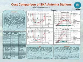
12m Composite Antenna Manufacturing Study Production costing numbers from a Profile Composites study done on the CART 12m symmetric dish assuming 2 dish molds for phase 1 and 4 molds for phase 2.
More Detail From Contracts • Feasibility and Cost Study (Memo 116): • Phase 1, 620 dishes over 4 years, average 3.6 dishes per week, 2 molds required. • Phase 2, 3000 dishes over 4 years, average 16.7 dishes per week, 4 molds required. • A review of Creep in Carbon and Aramid Fiber Composites: • Creep not an issue except in area immediately around bolted attachment to base, and then only if stress levels are not kept low • Creep could be an issue with Kevlar fibers at higher stress levels • Weathering and Environmental Effects: • Weathering, not an issue if composite protected from elements with a good external paint or gelcoat layer • Carbon fiber and e-glass not subject to UV damage. Phenolic resin is also resistant to UV damage. • Vinylester, and epoxy resins, and Kevlar fiber are subject to UV damage but damage rate is low. • Wind tunnel Investigation of Symmetric and Offset Reflector Radio Telescopes: • A large non-dimensional data set was collected in 2009 for wind pressure contours on the frontside and backside of an offset and a prime focus antenna. Forces and moments were also measured at the telescope mount. The tests were also done with and without a secondary mirror.