Download
1 / 14
140 likes | 539 Views
Contents. Introduction to the companyOverview of how FME is used across the companyDetailed case study into of how FME enables Landmark to provide data solutionsKey benefits of using FME. Who are we?. ArchitectsEngineersSurveyorsEnvironmental ConsultantsDevelopersEstate agentsConveyancersLocal governmentUtility companies.

E N D
1. De-mystifying LiDAR data: 3D topography solutions for CAD and GIS users Matt Wills � GIS Analyst 07th April 2011 Introduction:
Name
Role
Title of presentation
Next Slide: Introduction to presentationIntroduction:
Name
Role
Title of presentation
Next Slide: Introduction to presentation
2. Contents Introduction to the company
Overview of how FME is used across the company
Detailed case study into of how FME enables Landmark to provide data solutions
Key benefits of using FME Introduction
�
Introduction to the company
Overview of how FME is used across the company
Detailed case study into of how FME enables Landmark to provide data solutions
Key benefits of using FME
Next Slide: Who are Landmark?Introduction
�
Introduction to the company
Overview of how FME is used across the company
Detailed case study into of how FME enables Landmark to provide data solutions
Key benefits of using FME
Next Slide: Who are Landmark?
3. Who are we? Architects
Engineers
Surveyors
Environmental Consultants
Developers
Estate agents
Conveyancers
Local government
Utility companies Who is Landmark?
What is our market?
�
Landmark was established in 1995 and provides a wide range of data and services relating to the property market.
We provide information, data and services to a broad range of environmental and property professionals:
Different fields
Different requirements
Range of skills/software
Key Point - Data accuracy is important
Next Slide: what do we do?Who is Landmark?
What is our market?
�
Landmark was established in 1995 and provides a wide range of data and services relating to the property market.
We provide information, data and services to a broad range of environmental and property professionals:
Different fields
Different requirements
Range of skills/software
Key Point - Data accuracy is important
Next Slide: what do we do?
4. What do we do? Ordnance Survey Partner What do we do?
�
Environmental data & reports (environmental professionals, conveyancers)
Current and historic mapping (environmental professionals, conveyancers)
Floor plans (for estate agents)
Valuation information (for lenders)
Geospatial solutions and managed services (Landmark Solutions)
�
Partner Ordnance Survey company (re-selling OS Data)
�
Next Slide: How do we use FME?
What do we do?
�
Environmental data & reports (environmental professionals, conveyancers)
Current and historic mapping (environmental professionals, conveyancers)
Floor plans (for estate agents)
Valuation information (for lenders)
Geospatial solutions and managed services (Landmark Solutions)
�
Partner Ordnance Survey company (re-selling OS Data)
�
Next Slide: How do we use FME?
5. How do we use FME? How do we use FME?
�
Key Point - FME used at many levels in the company:
�
Bespoke data conversion/translation using FME Workbench (2009/2010)
Loading and extracting data to/from corporate Oracle Spatial database
Bulk data conversion using FME Server
Next Slide: Take one specific example of how we use FME to provide data solutions for customers
�
How do we use FME?
�
Key Point - FME used at many levels in the company:
�
Bespoke data conversion/translation using FME Workbench (2009/2010)
Loading and extracting data to/from corporate Oracle Spatial database
Bulk data conversion using FME Server
Next Slide: Take one specific example of how we use FME to provide data solutions for customers
�
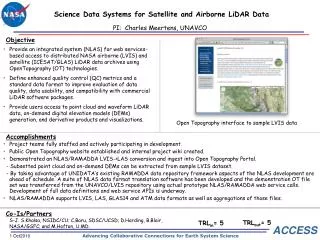
6. Case Study - 3D topography solutions for CAD and GIS users Landmark are re-sellers of the Environment Agency�s LiDAR Digital Elevation Data
Case Study - Employing FME to provide 3D topography solutions for CAD and GIS users
�
LIG are re-sellers of the Environment Agency�s LiDAR Digital Elevation Data
�
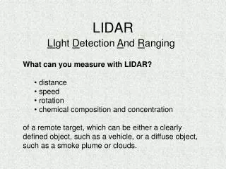
What is LiDAR?
�
Stands for Light Detection and Ranging
Similar to Radar, but uses beams of light (higher precision and weather independent)
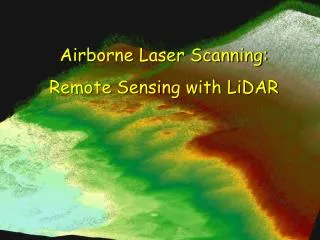
Used to quickly survey and produce detailed elevation models (aerial surveys of entire landscapes, or detailed localised surveys from ground mounted capture devices)
Key Point � high density, high accuracy data covering large extents
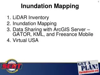
The EA DEM covers large areas of the country (areas at risk of flooding) and is available in 2 forms:
DSM
DTM (explain differences)
�
How is it Used?
�
Range of uses � flood modelling, civil engineering, planning, line of sight and visualisation
Range of users � from simple context to detailed site analysis
Next Slide: What does the EA provide?Case Study - Employing FME to provide 3D topography solutions for CAD and GIS users
�
LIG are re-sellers of the Environment Agency�s LiDAR Digital Elevation Data
�
What is LiDAR?
�
Stands for Light Detection and Ranging
Similar to Radar, but uses beams of light (higher precision and weather independent)
Used to quickly survey and produce detailed elevation models (aerial surveys of entire landscapes, or detailed localised surveys from ground mounted capture devices)
Key Point � high density, high accuracy data covering large extents
The EA DEM covers large areas of the country (areas at risk of flooding) and is available in 2 forms:
DSM
DTM (explain differences)
�
How is it Used?
�
Range of uses � flood modelling, civil engineering, planning, line of sight and visualisation
Range of users � from simple context to detailed site analysis
Next Slide: What does the EA provide?
7. Case Study - 3D topography solutions for CAD and GIS users Case Study - Employing FME to provide 3D topography solutions for CAD and GIS users
Key Point - Data only supplied in limited formats � ASCII grid/Text points (JPEG does not actually contain any elevation information)
�
ASCII grid is simply a regular array of height values (cell size varies with resolution)
Key Point - Data only supplied in full NG tiles (500m or 1km depending on resolution)
What are the problems/limitations associated with the data?
File sizes
ASCII/txt formats for use in GIS and dedicated 3D modelling software
Limited use to CAD users in its native format
Too many features for CAD to ingest easily (1km2 of data can easily contain 1,000,000 features)
GIS users may require additional software/add-ons to get the full benefit from the data
Next Slide: At this stage we didn�t have the solution� What can FME do? Case Study - Employing FME to provide 3D topography solutions for CAD and GIS users
Key Point - Data only supplied in limited formats � ASCII grid/Text points (JPEG does not actually contain any elevation information)
�
ASCII grid is simply a regular array of height values (cell size varies with resolution)
Key Point - Data only supplied in full NG tiles (500m or 1km depending on resolution)
What are the problems/limitations associated with the data?
File sizes
ASCII/txt formats for use in GIS and dedicated 3D modelling software
Limited use to CAD users in its native format
Too many features for CAD to ingest easily (1km2 of data can easily contain 1,000,000 features)
GIS users may require additional software/add-ons to get the full benefit from the data
Next Slide: At this stage we didn�t have the solution� What can FME do?
8. Case Study - 3D topography solutions for CAD and GIS users Case Study - Employing FME to provide 3D topography solutions for CAD and GIS users
�
Merge data into a single file
Clip data to site
Customer only pays for the data they need
Key Point � particularly useful if site located across multiple tiles
Next Slide: What other solutions can Landmark offer using FME?Case Study - Employing FME to provide 3D topography solutions for CAD and GIS users
�
Merge data into a single file
Clip data to site
Customer only pays for the data they need
Key Point � particularly useful if site located across multiple tiles
Next Slide: What other solutions can Landmark offer using FME?
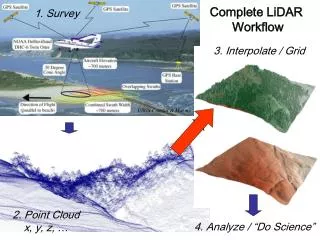
9. Case Study - 3D topography solutions for CAD and GIS users Using FME, Landmark are able to offer the following additional outputs: How do we use FME to provide solutions?
��
In addition to the ASCII, TXT and JPEG formats, LIG can use FME to offer the following outputs:
Points
Contours
TIN model
2D data suitable for both CAD & GIS users
3D data suitable for CAD users
What is a TIN Model?
TIN � triangulated irregular network (or triangular inferred network)
Efficient method of representing a surface (in this case a terrain) using triangles
Derived 3D model for use in CAD packages (not just a straight format translation)
CAD users can easily create surfaces from TIN/Contours
Some CAD systems can ingest the source ASCII grid and generate a TIN, but this creates a pair of triangles for each cell in the source file as well as the following problems:
Inflated file size
Not clipped to site
Problems around the edge of the tile
FME�s SurfaceModeller produces an optimised TIN Model (and contours) suitable for CAD users
Large triangles for flat areas, more & smaller triangles to represent complex terrain
Because LIG are offering the facility to clip the ASCII data to an irregular shape, this facility is also offered for the AutoCAD dwg formats (TIN, Contours)How do we use FME to provide solutions?
��
In addition to the ASCII, TXT and JPEG formats, LIG can use FME to offer the following outputs:
Points
Contours
TIN model
2D data suitable for both CAD & GIS users
3D data suitable for CAD users
What is a TIN Model?
TIN � triangulated irregular network (or triangular inferred network)
Efficient method of representing a surface (in this case a terrain) using triangles
Derived 3D model for use in CAD packages (not just a straight format translation)
CAD users can easily create surfaces from TIN/Contours
Some CAD systems can ingest the source ASCII grid and generate a TIN, but this creates a pair of triangles for each cell in the source file as well as the following problems:
Inflated file size
Not clipped to site
Problems around the edge of the tile
FME�s SurfaceModeller produces an optimised TIN Model (and contours) suitable for CAD users
Large triangles for flat areas, more & smaller triangles to represent complex terrain
Because LIG are offering the facility to clip the ASCII data to an irregular shape, this facility is also offered for the AutoCAD dwg formats (TIN, Contours)
10. Case Study - 3D topography solutions for CAD and GIS users Clip the full TIN How do we use FME to provide solutions?
Not straightforward�
Use the clipped ASCII grids as the input:
SurfaceModeller has problems resolving the extents
Clip the full TIN:
Clipping extents are 2D
Triangles on edge are pinned to zero elevation
Triangles within site are 3D
Clip using 3D clipping extents:
Breaks the triangles on the edge
No longer a Triangular network
Next Slide: How do we use FME to provide these additional options?
How do we use FME to provide solutions?
Not straightforward�
Use the clipped ASCII grids as the input:
SurfaceModeller has problems resolving the extents
Clip the full TIN:
Clipping extents are 2D
Triangles on edge are pinned to zero elevation
Triangles within site are 3D
Clip using 3D clipping extents:
Breaks the triangles on the edge
No longer a Triangular network
Next Slide: How do we use FME to provide these additional options?
11. Case Study - 3D topography solutions for CAD and GIS users FME Transformer � in detail
Main transformer used to clip the source ASCII file and produce the clipped TIN and Contours
2D and 3D points created from the clipped ASCII using a separate FME workspace
�
Feed in customer�s sites extents (MapInfo/DXF/SHP) & source data (ASCII and/or JPG)
Remove unnecessary attributes and mosaic source ASCII files into a single input
Create bounding box
Create surface using SurfaceModeller
Clip extents
Apply text labels to contour outputs
Write output formats
Next Slide: Resolving the problems when creating a clipped surface modelFME Transformer � in detail
Main transformer used to clip the source ASCII file and produce the clipped TIN and Contours
2D and 3D points created from the clipped ASCII using a separate FME workspace
�
Feed in customer�s sites extents (MapInfo/DXF/SHP) & source data (ASCII and/or JPG)
Remove unnecessary attributes and mosaic source ASCII files into a single input
Create bounding box
Create surface using SurfaceModeller
Clip extents
Apply text labels to contour outputs
Write output formats
Next Slide: Resolving the problems when creating a clipped surface model
12. Case Study - 3D topography solutions for CAD and GIS users Creating a clipped 3D Surface
Flexibility of FME enables us to build a process in stages, replicating the processes that would be undertaken in CAD/GIS to achieve the same result
Use the SurfaceDraper in conjunction with the SurfaceModeller
Perform multiple iterations
Read in the source site extents as a 2D vector
The full rectangular TIN model is generated from the source ASCII grids
The source digitised area used for the clipping extents is draped over the model in order to derive a 3D vector model of the clipping boundary
This 3D clipping extent is then fed into a second SurfaceModeller as a Breakline, along with the source ASCII grid in order to recreate the TIN based on these new extents. This Breakline introduces a hard boundary in the TIN model and ensures that all triangles neatly butt up to these extents
�
The resulting TIN model is then clipped using this 3D clipping boundary in order to output the final irregular TIN
Next Slide: Transformers used, and key features
Creating a clipped 3D Surface
Flexibility of FME enables us to build a process in stages, replicating the processes that would be undertaken in CAD/GIS to achieve the same result
Use the SurfaceDraper in conjunction with the SurfaceModeller
Perform multiple iterations
Read in the source site extents as a 2D vector
The full rectangular TIN model is generated from the source ASCII grids
The source digitised area used for the clipping extents is draped over the model in order to derive a 3D vector model of the clipping boundary
This 3D clipping extent is then fed into a second SurfaceModeller as a Breakline, along with the source ASCII grid in order to recreate the TIN based on these new extents. This Breakline introduces a hard boundary in the TIN model and ensures that all triangles neatly butt up to these extents
�
The resulting TIN model is then clipped using this 3D clipping boundary in order to output the final irregular TIN
Next Slide: Transformers used, and key features
13. Case Study - 3D topography solutions for CAD and GIS users Transformers Used and Key Features
Simple transformers, used in a particular order
Raster Mosaicker
Surface Modeller (x2)
Surface Draper
Clipper
Key Features:
Clip to site
Multiple formats
Key benefits to customer:
Ready to use data
Clipped to site
Optimised files size
Different options depending on application
Saves customer time and money
Next Slide: Key benefits of using FME
Transformers Used and Key Features
Simple transformers, used in a particular order
Raster Mosaicker
Surface Modeller (x2)
Surface Draper
Clipper
Key Features:
Clip to site
Multiple formats
Key benefits to customer:
Ready to use data
Clipped to site
Optimised files size
Different options depending on application
Saves customer time and money
Next Slide: Key benefits of using FME
14. Case Study - 3D topography solutions for CAD and GIS users Key Benefits (to Landmark)
�
Confidence � we know there will be a solution
Flexible � we can develop the solution iteratively as the situation/resources allow
Accuracy � as data resellers we need to ensure we are not removing information
Scalable � using FME Server we can incorporate solutions into repeatable packages
Key Point - Similar benefits apply to other areas where FME is used
Next Slide: End
Key Benefits (to Landmark)
�
Confidence � we know there will be a solution
Flexible � we can develop the solution iteratively as the situation/resources allow
Accuracy � as data resellers we need to ensure we are not removing information
Scalable � using FME Server we can incorporate solutions into repeatable packages
Key Point - Similar benefits apply to other areas where FME is used
Next Slide: End