Download
1 / 14
140 likes | 263 Views
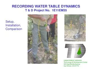
RECORDING WATER TABLE DYNAMICS T & D Project No. 1E11EM35. Setup, Installation, Comparison. USDA FOREST SERVICE Technology & Development Center 444 East Bonita Avenue San Dimas, CA 91773. Setup and Installation Materials. Well screen and point suitable for soil type

E N D
RECORDING WATER TABLE DYNAMICST & D Project No. 1E11EM35 Setup, Installation, Comparison USDA FOREST SERVICE Technology & Development Center 444 East Bonita Avenue San Dimas, CA 91773
Setup and InstallationMaterials • Well screen and point suitable for soil type • Sandy soils often require metal points, screens and pipe to allow driving the well appreciably below immediate water table • Soils not susceptible to sloughing below the water table will accept PVC points, screens and pipes without excessive driving • 2” pipe (UV-resistant preferred if PVC), 2” slip-connect unions, and pipe cement
Setup and InstallationMaterials An effective well screen is essential for accurate water table measurements. This provider determined appropriate screen size based on a description of the soil type. Brady Products, Inc. 2151 Logan St. P.O. Box 5304 Clearwater, FL 34618 Toll free (800) 237-6900 Florida (800) 282-6900
Setup and InstallationMaterials • Data logger unit designed for 2” well (all units tested are acceptable) • Metal locking well cap, mounting screws, screwdriver, drill, and lock • Well auger, well screen, slide hammer suitable for driving pipe below water table, saw suitable for cutting pipe to length • Laptop or palmtop computer for testing and setting up units after installation
2-⅜ ” 2-⅜ ” Well cap base secured to PVC pipe by short machine screws. Screws are securely shrouded by locking well cap. Setup and Installation
Setup and InstallationLocking well cap provider • Royer Quality Castings, Inc. 380 S. Reading Ave. (Rear) Boyertown, PA 19512-1812 (610) 367-1390 Fax (610) 367-8435 -Padlocks and keys available from same supplier
Setup and Installation The caps received required some grinding to remove burrs left over from casting.
Setup and Installation All units tested are compatible with 2” well diameters. Ordering options generally include various cable lengths. All cables can be shortened considerably by winding extra cable around a ½” diameter stick at the top of the well (see next slide).
Setup and Installation The InSitu sensor is the only sensor that can be detached from its cable in the field. This allows the installer to carry several cable lengths for one sensor when water table depths are not known before installation. This reduces the need to wrap cable. Sensors must be suspended above the bottom of the well. Pipes frequently need to be driven several feet below the water table to allow accurate measurement at greatest depth.
Setup and Installation The unique suspending collar installed on the In-Situ cable required an alternative installation to allow later retrieval without destroying the well. The plastic locking well cap provided with the unit inspired little confidence in the unit’s security, though the company is interested in providing metal locking caps on demand.
Setup and Installation Notice the two locks necessary to allow nondestructive removal of the In-Situ unit (left). The Sutron logger head (center) requires the tallest well stack to allow measurements up to ground level. The Global requires a considerably shorter stack, and the In-Situ would require nearly no stack (and only one lock) if the cable was not coiled inside. Coiled cable and cable ends must be suspended above the highest possible water level.
In-Situ MiniTROLL Sutron DWLMS Global Water WL15 Unidata 8007WDP Solinst Levelogger No pressure compensation Stevens SDI-12 Depth Sensor Logging option not designed for 2” well Vadoscan water level sensor Inadequate memory 2-Inch Well Compatible Equipment Tested Models Untested Models This is not a comprehensive listing. The above products are a sampling of those commercially available at the time of the project market search.
Unit Comparisons • Palmtop data collection with In-Situ unit allows more convenient monitoring in all conditions • Global Water also releasing palmtop-compatible software • Global unit contains no desiccant to replace • Sutron log records errors and notes as well as data
Unit Comparisons • In-Situ data management more user-friendly; much more difficult to accidentally lose data • Installation of all units much easier when coiling cable can be avoided