Download
1 / 18
180 likes | 209 Views
This presentation covers the fundamental laws and configurations in electric circuits, including Ohm's Law, circuit setup, series vs. parallel circuits, nodal definitions, and Kirchhoff's laws. Learn to solve for resistance, current, and voltage in series and parallel setups.

E N D
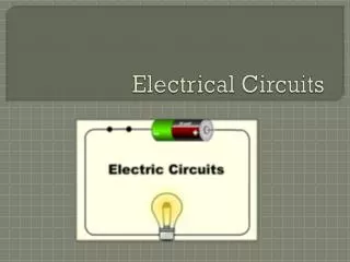
Electrical Circuits • This presentation will Discuss the basic laws in electric circuits • Topics discussed are: • Ohm’s Law • Circuit configuration • Series, parallel circuits • Definitions of Nodes and branches • Kirchhoff’s laws statements • Procedure to solve series circuits for Resistance, current and voltage • Procedure to solve parallel circuits for Resistance, current and voltage Objectives: • This work is licensed under aCreative Commons Attribution 4.0 International License. • PPT submitted by RC 1353_810, RVR&JCCE, Guntur Creative Commons Attribution-ShareAlike 4.0 International License. You are free to use, distribute and modify it, including for commercial purposes, provided you acknowledge the source and share-alike.
Ohm’s Law • Defines the relationship between voltage, current, and resistance in an electric circuit • Ohm’s Law: Current in a resistor varies in direct proportion to the voltage applied to it and is inversely proportional to the resistor’s value. • Stated mathematically: V + - I R • Where: I is the current (amperes) • V is the potential difference (volts) • R is the resistance (ohms)
Ohm’s Law Triangle • Example: • The flashlight shown uses a 6 volt battery and has a bulb with a resistance of 150 . When the flashlight is on, how much current will be drawn from the battery? V V I I R R Solution: Schematic Diagram IR + - VT = VR
Circuit Configuration Components in a circuit can be connected in one of two ways. Parallel Circuits Both ends of the components are connected together. There are multiple paths for current to flow. Series Circuits • Components are connected end-to-end. • There is only a single path for current to flow. Components (i.e., resistors, batteries, capacitors, etc.)
Series Circuits Characteristics of a series circuit The current flowing through every series component is equal. The total resistance (RT) is equal to the sum of all of the resistances (i.e., R1 + R2 + R3). The sum of all of the voltage drops (VR1 + VR2 + VR2) is equal to the total applied voltage (VT). This is called Kirchhoff’s Voltage Law.
Parallel Circuits Characteristics of a Parallel Circuit The voltage across every parallel component is equal. The total resistance (RT) is equal to the reciprocal of the sum of the reciprocal: The sum of all of the currents in each branch (IR1 + IR2 + IR3) is equal to the total current (IT). This is called Kirchhoff’s Current Law. IT + + + + VR1 VR2 VR3 VT - - - - RT
Nodes and Branches • A node is defined as a point of connection of two or more circuit elements. • An essential node is defined as a point of connection of three or more circuit elements. • Branch, an open path in a circuit including one or more circuit elements and no essential nodes
Kirchhoff’s Laws • Kirchhoff’s Voltage Law (KVL): • The sum of all of the voltage drops in a series circuit equals the total applied voltage. Gustav Kirchhoff 1824-1887 German Physicist • Kirchhoff’s Current Law (KCL): • The total current in a parallel circuit equals the sum of the individual branch currents. Picture courtesy : Wikipedia
Series Circuits Characteristics of a series circuit • The current flowing through every series component is equal. • The total resistance (RT) is equal to the sum of all of the resistances (i.e., R1 + R2 + R3). • The sum of all of the voltage drops (VR1 + VR2 + VR2) is equal to the total applied voltage (VT). This is called Kirchhoff’s Voltage Law. VR1 IT + - + + VR2 VT - - - + RT VR3
Example: Series Circuit • Example: • For the series circuit shown, use the laws of circuit theory to calculate the following: • The total resistance (RT) • The current flowing through each component (IT, IR1, IR2, & IR3) • The voltageacross each component (VT, VR1, VR2, & VR3) • Use the results to verify Kirchhoff’s Voltage Law. VR1 IT + - IR1 + + VR2 VT IR2 - - IR3 - + RT VR3
Example: Series Circuit Current Through Each Component: Solution: Total Resistance: V V I I R R Voltage Across Each Component: Verify Kirchhoff’s Voltage Law:
Parallel Circuits Characteristics of a Parallel Circuit • The voltage across every parallel component is equal. • The total resistance (RT) is equal to the reciprocal of the sum of the reciprocal: • The sum of all of the currents in each branch (IR1 + IR2 + IR3) is equal to the total current (IT). This is called Kirchhoff’s Current Law. IT + + + + VR1 VR2 VR3 VT - - - - RT
Example: Parallel Circuit • Example: • For the parallel circuit shown, use the laws of circuit theory to calculate the following: • The total resistance (RT) • The voltageacross each component (VT, VR1, VR2, & VR3) • The current flowing through each component (IT, IR1, IR2, & IR3) • Use the results to verify Kirchhoff’s Current Law. IT IR1 IR2 IR3 + + + + VR1 VR2 VR3 VT - - - - 14 RT
Example: Parallel Circuit Solution: Voltage Across Each Component: Total Resistance: V I R Verify Kirchhoff’s Current Law: Current Through Each Component:
Summary: In this presentation, We have seen The statements of Ohm’s Law The concepts of Nodes, branches, series, parallel circuits Kirchhoff’s voltage law Kirchhoff’s current law The procedure to solve Series circuits Parallel circuits NOW, TRY THE FOLLOWING PROBLEMS
LEARN BY DOING(LbD) 1. Find the total resistance for the resistor circuit shown in the Figure. 2. For the DC circuit shown in the Figure, find the voltage across each resistor and the current in each resistor.
LEARN BY DOING(LbD) 3. For the DC circuit shown in the Figure, find the voltage across each resistor and the current in each resistor. Find the power dissipations in the 2 Ω, 5 Ω and 22 Ω resistors. 4. For the DC circuit shown in the Figure, find the voltage across each resistor and the current in each resistor.