Download
1 / 6
60 likes | 147 Views
Explore the intricate processes of the LHC cycles, bunch injections, controlled blow-ups, and the development of coupled-bunch instabilities. Learn about feedback mechanisms, RF cavity manipulations, and the management of transient beam loading effects. Discover observations in longitudinal coupled-bunch oscillations, mode spectra during acceleration, and asymmetry corrections in bunch profiles. Find out about the upcoming enhancements for improved system performance and efficiency.

E N D
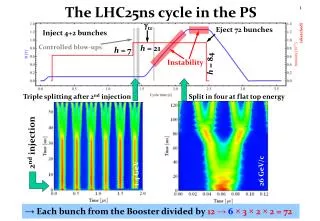
The LHC25ns cycle in the PS gtr Eject 72 bunches Inject 4+2 bunches (sketched) Controlled blow-ups h = 21 h = 7 Instability h = 84 Triple splitting after 2nd injection Split in four at flat top energy 2nd injection 1.4 GeV 26 GeV/c →Each bunch from the Booster divided by 12 → 6 × 3 × 2 × 2 = 72
The LHC50ns cycle in the PS Eject 36 bunches Inject 4+2 bunches gtr Instability Controlled blow-ups h = 21 h = 7 h = 84 Triple splitting after 2nd injection Split in two at flat top energy 2ndinjection 1.4 GeV 26 GeV/c → Each bunch from the Booster divided by 6 → 6 × 3 × 2 = 36
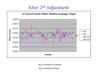
Longitudinal coupled-bunch observations • Without RF manipulations on the flat-top: Slowly (~100 ms) developing dipolar and quadrupolar coupled-bunch instabilities Ejection Analyze couple-bunch mode amplitudes and spectrum
Longitudinal coupled-bunch instabilities Acceleration Flat-top 25 ns g = 27.2 • During acceleration: • No resonant excitation of modes • Main RF cavities are dominant impedance • Different mode spectrum on the flat-top: • Driving impedance changes • Reducing impedance by short-circuiting 9/10 cavities • Instabilities with 25 ns and 50 ns bunch spacing very similar Mode spectrum during acceleration g = 10.8
Longitudinal coupled-bunch instabilities • Coupled-bunch oscillations observed after transition crossing in the PS • Existing feedback system using RF cavities as longitudinal kickers Without FB Requires new FB Reachable with FB • Empiric scaling with longitudinal bunch density, Nb/el • MDs in 2012 • With present system coupled-bunch limit (25/50 ns) at about 1.9 1011 ppb el/2 • Dedicated wideband kicker (PS-LIU) to be installed during shut-down 2013/14 • Damp all possible modes from frev to fRF/2
Transient beam-loading during splitting • Transient beam loading causes small phase errors in RF cavities • Left-right intensity asymmetry of bunches after splitting along the batch Left bunch Right bunch Left/right asymmetry after splitting 10 cycle average Bunch profile integral Gauss fit integral • Improve and add 1-turn feedbacks against transient beam-loading to reduce bunch-to-bunch intensity and emittance spread • Maximize gain of direct wide-band feedbacks (10 MHz, 40 MHz, 80 MHz)


![Time after 2 nd salt treatment [hours]](https://cdn1.slideserve.com/2596494/slide1-dt.jpg)