Download
1 / 20
210 likes | 521 Views
Understand phasor diagrams for voltage and current in series RLC circuits, impedance relations, resonance, and power factors in AC circuits. Learn how to apply sinusoidal AC sources, Kirchhoff's rules, and analyze circuit response in the steady state.

E N D
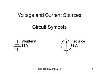
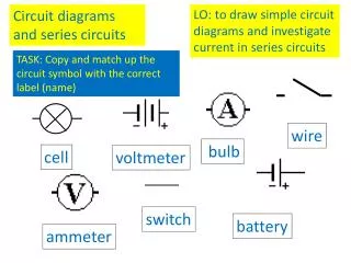
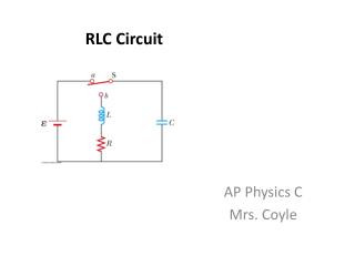
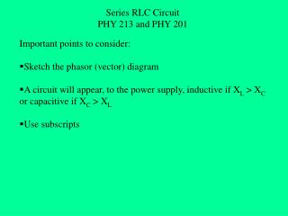
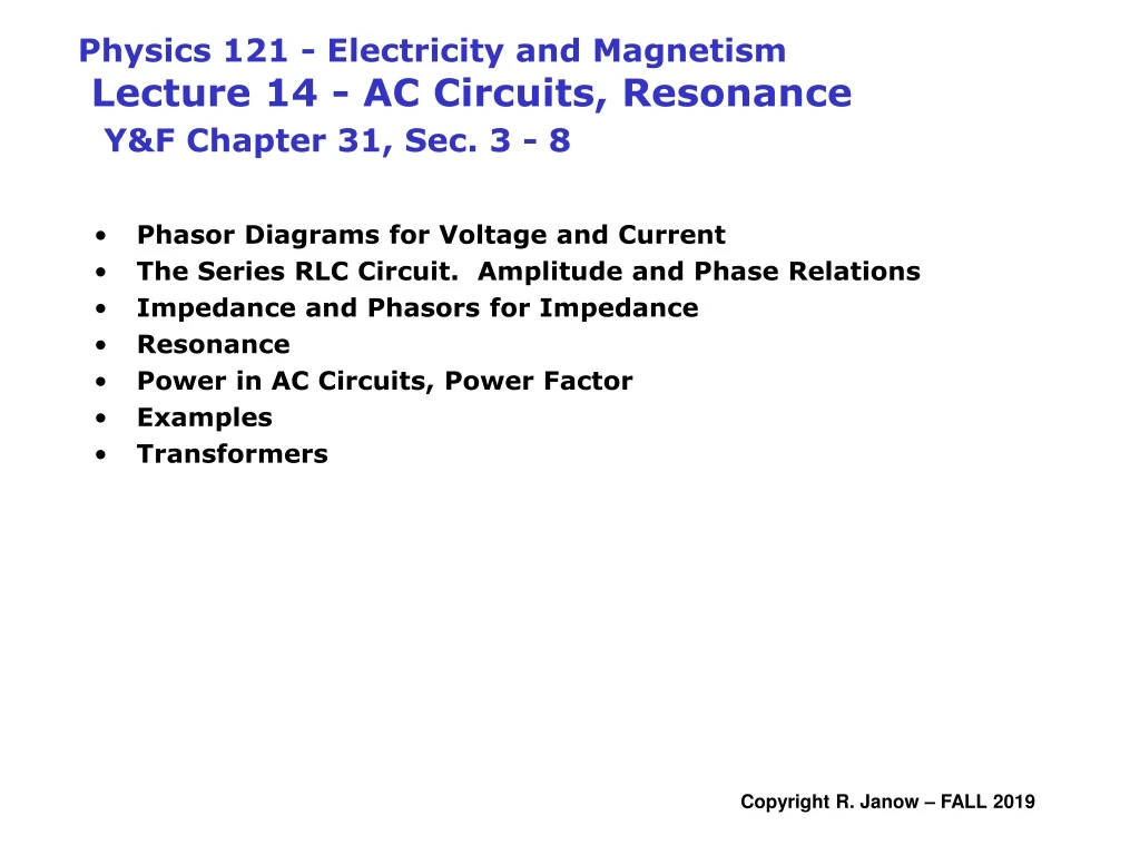
Physics 121 - Electricity and Magnetism Lecture 14 - AC Circuits, ResonanceY&F Chapter 31, Sec. 3 - 8 • Phasor Diagrams for Voltage and Current • The Series RLC Circuit. Amplitude and Phase Relations • Impedance and Phasors for Impedance • Resonance • Power in AC Circuits, Power Factor • Examples • Transformers
load the driving frequency STEADY STATE RESPONSE (after transients die away): . Current in load is sinusoidal, has same frequency as source ... but . Current may be retarded or advanced relative to E by “phase angle” F for the whole circuit(due to inertia L and stiffness 1/C). resonant frequency peak applied voltage DEFINE: IMPEDANCE IS THE RATIO OF PEAK (or RMS) EMF TO PEAK (or RMS) CURRENT. peak current • Impedance for a circuit is a function of resistances, reactances, and how they are interconnected Apply Sinusoidal AC Source to Circuit KIRCHHOFF RULES APPLY: . In a series branch, current has the same amplitude and phase everywhere. . Across parallel branches, voltage drops have the same amplitudes and phases . At nodes (junctions), instantaneous net currents in & out are conserved
Current/Voltage Phases in Resistors, Capacitors, and Inductors VR& Im in phase Resistance VC lags Im by p/2 Capacitive Reactance VL leads Im by p/2 Inductive Reactance Same Phase currrent • Sinusoidal current i(t) = Imcos(wDt). Peak is Im • vR(t) ~ i(t) vL(t) ~ derivative of i(t) Vc(t) ~ integral of i(t) • Peak voltages across R, L, or C lead/lag current by 0, p/2, -p/2 radians • Ratios of peak voltages to peak currents are called Reactances in C’s and L’s • Phases of voltages in a series branch are relative tothe current phasor.
Applied EMF: vR Current: E R L vL C vC F Im Em wDt+F wDt Instantaneous voltages add normally (Loop Rule) VL Em Im • Phasors for VR, VL, & VC all rotate at wD : • VClags Im by p/2 • VR has same phase as Im • VLleads Im by p/2 F wDt VR Phasor magnitudes add like vectors VC along Im perpendicular to Im Phasors applied to a Series LCR circuit Same current including phase everywhere in the single branch • Refer voltage phasors to current phasor • Everything oscillates at the driving frequency wD • Same phase for the current in E, R, L, & C, but...... • Current leads or lags E (t) by a constant phase angle F
Impedance functions for a Series LCR Circuit Voltage peak addition rule in series circuit: Em Im F VL-VC Z Reactances: XL-XC VR wDt R Same peak current flows in each component: Divide each voltage in |Em| by (same) peak current: Applies to a single series branch with L, C, R Magnitude of Z: F measures the power absorbed by the circuit: Phase angle F: See phasor diagram • RESONANCE: XL=XC Im parallel to Em F = 0 Z = R maximum current F is zero circuit acts purely resistively. • Otherwise: F >0 (current lags EMF) or F<0 (current leads EMF) • R ~ 0 Im normal to Em F ~ +/- p/2 tiny losses, no power absorbed
vR Circuit Element Symbol Resistance or Reactance Phase of Current Phase Angle Amplitude Relation E R Resistor R R In phase with VR 0º (0 rad) VR = ImR L vL C Capacitor C XC=1/wdC Leads VC by 90º -90º (-p/2) VC = ImXC vC Inductor L XL=wdL Lags VL by 90º +90º (p/2) VL = ImXL Em Im F VL-VC Z VR XL-XC wDt R sketch shows XL > XC Summary: AC Series LCR Circuit
A series RLC circuit has R = 425 Ω, L = 1.25 H, C = 3.50 μF. It is connected to an AC source with f = 60.0 Hz and εm= 150 V. Determine the impedance of the circuit. Find the amplitude of the current (peak value). Find the phase angle between the current and voltage. Find the instantaneous current across the RLC circuit. Find the peak and instantaneous voltages across each circuit element. Example 1: Analyzing a series RLC circuit
Determine the impedance of the circuit. Angular frequency: Resistance: Inductive reactance: Capacitive reactance: Current phasor Im leads the Voltage Em Phase angle will be negative XC > XL (Capacitive) (B) Find the peak current amplitude: • Find the phase angle between the current and voltage. Example 1: Analyzing a Series RLC circuit A series RLC circuit has R = 425 Ω, L = 1.25 H, C = 3.50 μF. It is connected to an AC source with f = 60.0 Hz and εm=150 V.
Add voltages above: What’s wrong? Voltages add with proper phases: Example 1: Analyzing a series RLC circuit - continued A series RLC circuit has R = 425 Ω, L = 1.25 H, C = 3.50 μF. It is connected to an AC source with f = 60.0 Hz and εm=150 V. • Find the instantaneous current in the RLC circuit. (E) Find the peak and instantaneous voltages in each circuit element. VR in phase with Im VR leads Em by |F| = 0 VL leads VR by p/2 VC lags VR by p/2
Resonance in a series LCR Circuit: Example 2: Em = 100 V. R = 3000 W L = 0.33 H C = 0.10 mF vR Find |Z| and F for fD = 200 Hertz, fD = 876 Hz, & fD = 2000 Hz E R Why should fD make a difference? L vL C vC Frequency f Resistance R Reactance XC Reactance XL Impedance |Z| Phase Angle F Circuit Behavior 200 Hz 3000 W 7957 W 415 W 8118 W - 68.3º Capacitive Em lags Im 876 Hz 3000 W 1817 W 1817 W 3000 W Resonance 0º Resistive Max current 2000 Hz 3000 W 796 W 4147 W 4498 W +48.0º Inductive Em leads Im Em Im Im Em F < 0 F > 0 Im F=0 Em
E R L C width of resonance (selectivity, “Q”) depends on R. Large R less selectivity, smaller current at peak inductance dominates current lags voltage capacitance dominates current leads voltage damped spring oscillator near resonance Resonance in a series LCR circuit Vary wD: At resonance maximum current, minimum impedance
Power in AC Circuits • Resistors always dissipate power, but the instantaneous rate varies as i2(t)R • No power is lost in pure capacitors and pure inductors in an AC circuit • Capacitor stores energy during two 1/4 cycle segments. During two other segments energy is returned to the circuit • Inductor stores energy when it produces opposition to current growth during two ¼ cycle segments (the source does work). When the current in the circuit begins to decrease, the energy is returned to the circuit
Instantaneous power • Power is dissipated in R, not in L or C • cos2(x) is always positive, so Pinst is always • positive. But, it is not constant. • Power pattern repeats every p radians (t/2) The average or RMS power is the AC equivalent to DC power Integrate Pinst over t: Integral = 1/2 • RMS means “Root Mean Square” • Square a quantity (positive) • Average over a whole cycle • Compute square root. • COMPUTING RMS QUANTITIES: • For any RMS quantity divide peak • value such as Im or Em by sqrt(2) For any R, L, or C Household power example: 120 volts RMS 170 volts peak AC Power Dissipation in a Resistor
Power factor for an AC LCR Circuit The PHASE ANGLEF determines the average RMS power actually absorbed due to the RMS current and applied voltage in the circuit. How to compute power (proven below): Erms Irms F |Z| wDt XL-XC R Proof: Start with instantaneous power (not very useful): Average it over one full period t: Change variables: Use trig identity:
Power factor for AC Circuits - continued Odd integrand Even integrand Recall: RMS value = Peak value divided by sqrt(2) Also note: Alternate form: If R=0 (pure LC circuit)F +/- p/2 and Pav = Prms = 0
VR E R L VL C Find Erms: Find Irms at 200 Hz: VC Find the power factor: Find the phase angle F directly: Find the average power: or Example 2 continued with RMS quantities: Em = 100 V. R = 3000 W L = 0.33 H C = 0.10 mF fD = 200 Hz Recall: do not use arc-cos to find F
Example 3 – Use RMS values inSeries LCR circuit analysis F is positive since XL>XC (inductive) A 240 V (RMS), 60 Hz voltage source is applied to a series LCR circuit consisting of a 50-ohm resistor, a 0.5 H inductor and a 20 mF capacitor. Find the capacitive reactance of the circuit: Find the inductive reactance of the circuit: The impedance of the circuit is: The phase angle for the circuit is: The RMS current in the circuit is: The average power consumed in this circuit is: If the inductance is changed to maximize the current through the circuit, what new inductance L’ is needed? How much RMS current would flow in that case?
Transformers power transformer • Devices used to change • AC voltages. They have: • Primary winding • Secondary winding • Power ratings iron core circuit symbol
Ideal Transformer Assume: The same amount of flux FB cuts each turn in both primary and secondary windings in ideal transformer (counting self- and mutual-induction) iron core • zero resistance in coils • no hysteresis losses in iron core • all field lines are inside core Assuming no losses: energy and power are conserved Turns ratio fixes the step up or step down voltage ratio Vp, Vs are instantaneous (time varying) or RMS averages, as can be the power and current. Transformers Assume zero internal resistances, EMFs Ep, Es = terminal voltages Vp, Vs Faradays Law for primary and secondary:
Example: A dimmer for lights using a variable inductance Light bulb R=50 W Erms=30 V L b) What would be the change in the RMS current? P0,rms = 18 W. Without inductor: Prms = 5 W. With inductor: f =60 Hz w = 377 rad/sec Without Inductor: a) What value of the inductance would dim the lights to 5 Watts? Recall: