Download
1 / 37
370 likes | 595 Views
EKAS 2.18.2 Electrical Safe Working Practices. UEE31307 Certificate III in Refrigeration and Air Conditioning Stage 2A Units: UEENEEPOO1B, UEENEEPOO2B Chris Hungerford Friday, September 19, 2014. Principle and purpose of risk management.

E N D
EKAS 2.18.2Electrical Safe Working Practices UEE31307 Certificate III in Refrigeration and Air Conditioning Stage 2A Units: UEENEEPOO1B, UEENEEPOO2B Chris Hungerford Friday, September 19, 2014
Principle and purpose of risk management • The process of hazard identification, risk control and evaluation is the principle of risk management. • The purpose is the reduction of workplace incidents. 2..18.2.A
Workplace Safety Checks The five step risk management process Step 1: Identify all hazards by: •observing, inspecting, investigating, communicating and consulting •making a record of the hazards identified. 2..18.2.A
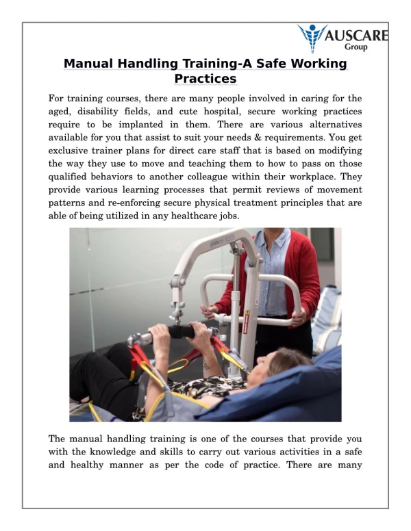
Identify all hazards in this photo. • electric shock, • falls, • slips, • Others ? Bent back Sunburn Jewellery Thongs 2..18.2.A
Workplace Safety Checks Step 2: Assess the risks these hazards create by: •assessing and prioritising the risks •dealing with the highest priority risks first •dealing with less risks or least significant risks last. • electric shock, • burns, • falls, • sunburn, • slips, • back injuries, 2..18.2.A
Workplace Safety Checks The five step risk management process Step 3: Decide on measures to control the risks by: •eliminating the risk -if elimination of the risk is not possible, select these control measures in the following order of preference: (i)substitution, (ii)isolation (not administrative), (iii)minimisation by engineering means (iv)application of administrative measures, (v)use of personal protective equipment (PPE). • electric shock, • burns, • falls, • sunburn, • slips, • back injuries, 2..18.2.A
Workplace Safety Checks Step 4: Implementing appropriate control measures should: •adequately control the risks •not create other risks •allow workers to do their work without undue discomfort or distress. • electric shock, • burns, • falls, • sunburn, • slips, • back injuries, 2..18.2.A
Workplace Safety Checks The five step risk management process Step 5: Monitor the control measures and review the process: A: Monitor •Have the control measures been implemented as intended? •Are the control measures adequate? •Did the implementation of control measures create other hazards or risks? B: Review •Has anything changed over time since the risk process was implemented? •Is the control of risks still adequate? •Was the risk management process conducted effectively? 2..18.2.A
Workplace Safety Checks 2..18.2.A
STANDARDS AUSTRALIA/STANDARDS NEW ZEALAND AS/NZS3000: 2007, including ADMT 1, July 2009. (known as the Australian/New Zealand Wiring Rules) 1.4.90 Voltage Differences of potential normally existing between conductors and between conductors and earth as follows: (a) Extra-low voltage Not exceeding 50 V a.c. or 120 V ripple-freed.c. (b) Low voltage Exceeding extra-low voltage, but not exceeding 1000 V a.c. or 1500 V d.c. (c) High voltage Exceeding low voltage. Standards online http://www.saiglobal.com/online/ id. 3690699457 Password IRCKRITFJP User name Skillstech 2..18.2.B
Extra Low Voltage 0-50vAC or 0-120vDC, examples: control circuits, printed circuit boards, indicators, battery operated devices, standby backup power, data, communications, small loads such as fans, low power heaters, pool lighting Types of Extra low voltage. Safety Extra-Low Voltage (SELV):protective-separation, double insulation from all circuits, other SELV, PELV and from earth. Example ELV lighting with own transformer. Protected extra-low voltage (PELV):only requires protective-separation from all circuits other than SELV and PELV but it may have connections to other PELV systems and earth. In contrast to a SELV circuit, a PELV circuit can have a protective earth connection. Example, control wiring in a large mechanical services switchboard. Functional extra-low voltage (FELV)is not adequately protected from accidental contact with higher voltages in other parts of the circuit. Therefore the protection requirements for the higher voltage have to be applied to the entire circuit. Circuits include those that generate an extra low voltage through a semiconductor device. Examples, switch mode power supply, UPS, variable speed controls. 2..18.2.B
Low Voltage system High Voltage 11-33kV 3 phases 240v each 415v between. Neutral Approx every 4-5 Pole MEN General load ie. AC, TV, light Low voltage. Low Voltage. Switchboard Low voltage. 2..18.2.B
Very high fault current near transformer 500kVA approx 13.5kA High Fault Currents At point of entry the resistance of the service lines reduce the current. Domestic approx = 10-6kA • Fault currents are limited by: • Size of transformer • CSA of conductors • Length of conductors. In a domestic Switchboard cable resistance has further reduce current to approx 5-3kA At a domestic load Fault current approx 1.5 -.5kA 2..18.2.B
High Voltage 11kv HV Switch room 11kV-240V Transformer Can be: pole mounted, Pad mounted, or in a transformer room 2..18.2.C
High voltage appliances • Microwave ovens………..2000V • Gas igniters ……………….15kV • Neon lighting………………10kV • Electro static devices • Photocopiers • Spray painters, powder coating • Dust suppression ………….10kV 2..18.2.C
Touch Voltage Touch voltage is caused by a fault current in a conductive material establishing a voltage between an earth contact point (feet) and another part of the body (hand) in contact with the energized material. 2..18.2.C
Step Potential When current is flowing thru the ground due to a ground fault, the voltage difference developed between two points on the ground separated by the distance of one pace is know as step potential. 2..18.2.C
Creepage Creepage is the shortest distance between two conductive parts and the surface of an insulator. 2..18.2.C
High Voltage ProceduresWhen working near HV. • Only be carried out on the authority of certified access permits and switching schedules. • Written lock out, isolation & switching events • Safety earthing, location in the field & methods of earthing plan. • Erection of safety barriers. • Identify any personal or business that will be interrupted. • All persons required to enter the work area are to sign the Permit to work access form. • When complete, all persons required to enter the work area also sign another form giving written authority for the re-energising of the supply. 2..18.2.C
Fibre Optics • Fibre optic cables consist of glass or polymer cores that should be treated equally with “medical sharps”. • Keep all food and beverages out of the work area. If fibre particles are ingested they can cause internal haemorrhaging. • Always wear safety glasses with side shields to protect your eyes from fibre shards or splinters. Treat fibre optic splinters the same as you would treat glass splinters. • Never look directly into the end of fibre cables – especially with a microscope – until you are positive that there is no light source at the other end – having tested it with a power meter. Use a fibre optic power meter to make certain the fibre is dark. When using an optical tracer or continuity checker, look at the fibre from an angle at least 6 inches away from your eye to determine if the visible light is present.. • Do not touch your eyes while working with fibre optic systems until your hands have been thoroughly washed. • Only work in well-ventilated areas. • Keep all combustible materials safely away from the curing ovens and fusion splicers. • Thoroughly clean your work area when you are done. 2..18.2.D
Class 3A Lasers Lasers in this class are mostly dangerous in combination with optical instruments which change the beam diameter or power density. Output power does not exceed 5 mW. Beam power density may not exceed 2.5 mW/square cm. Many laser sights for firearms and laser pointers are in this category. 2..18.2.D
3 Common Low Voltage Electrical Hazards. • Electric Shock. • Arcing : a short circuit can cause an intense arc of electrical energy and when released will result in burns. Fault currents of up to 20 times the rated can flow, Heat = I2R. • Toxic Gases: may be emitted during arcing which can cause adverse effect to a target human organ, may also contain carcinogens. 2..18.2.E
Risk with low voltage Electrical hazards: Electric shock, Arcing, toxic gases. • Exposed electrical parts • Contact with overhead services • Defective/inadequate insulation • Improper earthing of equipment • Overloaded circuits • Damaged test equipment and tools • Lack of training • Work not as per Australian & New Zealand standards. 2..18.2.E
Controlling Low voltage Hazards. The essential element for creating a safe work environment is to: • de-energise, • proving the circuit is dead, and • locking out of electrical equipment before making repairs. 2..18.2.E
Restrictions in working Live. ELECTRICAL SAFETY REGULATION 2002 11 Requirements for electrical work An employer or self-employed person must ensure that, unless thecircumstances required under this division for the performance of live workapply,live work is not performed. Maximum penalty—40 penalty units. 2..18.2.E
Control measures for working live. As per Regulation 12 “Requirement for performance of live work”, to perform live work you must satisfy the following seven (7) questions: Have you prepared a risk assessment? Is your test equipment appropriate to perform live work? Minimum Cat III @ 500v ac. Has your test equipment been maintained and confirmed that it is operating correctly? Regulation 18.2(b) “the instrument is tested at least every 6 mths to ensure it is in proper working order”, and Regulation 12.1(f) “the instrument is tested immediately prior to work to confirm that the instrument is operating correctly” Have you the correct PPE, (Safety boots, long pants, long sleeved shirt, insulated gloves, safety glasses)? As per AS/NZS 4836 Safe working on low voltage electrical installations. Is the isolation point clearly identified? Is the isolation point able to be reached without any obstructions? Is the area where the electrical live work is performed clear of any obstructions? 2..18.2.E
Control measures for working live. PPE. Headwear complying with AS/NZS 1801. Eye protection without metal frames and complying with AS/NZS 1337. Ear plugs or muffs complying with AS 1270. Flame retardant clothing covering the full body (including arms and legs) and not made from conductive material or containing metal threads. Insulating gloves Gloves complying with AS 2225 and insulated to the highest potential voltage expected for the work being undertaken, and Flame-resistant gloves Gloves complying with AS/NZS 2161.4 and protected against heat or fire to the highest level for the work being undertaken and air tested each time prior to use. Bling Watches, rings Bracelets, neck chains Ear rings, piercing Shoes or boots complying with AS/NZS 2210.2 and selected and maintained in accordance with AS/NZS 2210.1. 2..18.2.E
Harmful Dusts • Excessive dust emissions can cause both health and industrial problems: • Health hazards - Occupational respiratory diseases - Irritation to eyes, ears, nose and throat - Irritation to skin • Risk of dust explosions and fire • Damage to equipment • Impaired visibility • Unpleasant odours • Problems in community relations 2..18.2.F
Harmful Dusts Not all dusts product the same degree of health hazard; their harmfulness depends on the following factors: • Dust composition - Chemical - Mineralogical • Dust concentration -On a weight basis: milligrams of dust per cubic meter of air (mg/m3)-On a quantity basis: million particles per cubic foot of air (mppcf) • Particle size and shape - The particulate size distribution within the respirable range - Fibrous or spherical • Exposure time 2..18.2.F
Harmful Dusts Excessive or long-term exposure to harmful respirable dusts may result in a respiratory disease called pneumoconiosis. • Silicosis - Silicosis is a form of pneumoconiosis caused by the dust of quartz and other silicates. The condition of the lungs is marked by nodular fibrosis (scarring of the lung tissue), resulting in shortness of breath. Silicosis is an irreversible disease; advanced stages are progressive even if the individual is removed from the exposure. • Black Lung - Black lung is a form of pneumoconiosis in which respirable coal dust particles accumulate in the lungs and darken the tissue. This disease is progressive. Although this disease is commonly known as black lung, its official name is coal worker's pneumoconiosis (CWP). • Asbestosis - Asbestosis is a form of pneumoconiosis caused by asbestos fibres. This disease is also irreversible. 2..18.2.F
Harmful Dusts Reducing employee exposure to dust can be accomplished by three major steps: • Prevention. • Control Systems, dust collection systems, wet dust suppression systems • Dilution or Isolation. 2..18.2.F
Safety characteristics of Electrical testing devices Arc from transients (lightning, load switching) Protection: Independent certification to meet CAT III-1000 V or CAT IV 600 V Voltage contact while in continuity or resistance Protection: Overload (fuse) protection in OHMs up to the meter’s volt rating Measuring voltage with test leads in current jacks Protection: High energy fuses rated to the meter’s voltage rating Shock from accidental contact with live components Protection: Test Leads double insulated, recessed / shrouded, finger guards, CAT III – 1000 V. 2..18.2.G
Safe use of Electrical device • Don’t work alone. • Choose the correct device & range • Practice safe measurement techniques. • Always connect the grounded lead first, hot second. • Disconnect the hot lead first, grounded lead second. • Use the three-point test method. • Test known circuit, • measure target circuit, • then re-test known circuit. 2..18.2.G
Electricity Safety Regulation 2002 18 Employer or self-employed person to ensure suitability of testing instruments (1) This section applies to the following— (a) an employer of a person required to perform tests on electricalwork or safety equipment; (b) a self-employed person required to perform tests on electricalwork or safety equipment. (2) The employer or self-employed person must ensure— (a) the test instruments used for the testing are designed for, andcapable of correctly performing, the required tests; and (b) if a testing instrument can not be visually confirmed as beingcorrectly functioning and safe—that the instrument is tested atleast every 6 months to ensure it is in proper working order; and (c) records of tests performed are kept for at least 5 years. Maximum penalty for subsection (2)—40 penalty units. 2..18.2.G
S E C T I O N 6 T E S T E Q U I P M E N T AS/NZS 4836:2001 • 6.2 SUITABILITY OF EQUIPMENT • Test equipment shall pose no danger of electric shock to personnel or damage to the electrical equipment during testing. • Test equipment shall comply with the following: • Test equipment used in hazardous areas shall be of an approved design and shall be clearly marked as being suitable for use in such locations. • (b) Test probes and other equipment shall be designed and selected so that they cannot inadvertently short circuit between energized conductors and energized conductors and earth. • The terminals of test equipment should be shrouded and all other test sockets on measuring instruments should be designed so as to prevent inadvertent contact with any energized test socket and/or conductor when the equipment is in use. • Where appropriate, test leads and testing devices should be provided with suitable overcurrent protection. • NOTE: AS/NZS 2381 specifies requirements for the use of electrical equipment in hazardous 2..18.2.G
Care and Storage • Always handle carefully. • Practice cleanliness • Protect from knocks. • Store in a dry place. • Replace batteries yearly. • Remove batteries if you plan not to use your meter for extended periods. • Never replace the internal fuse with a larger fuse. 2..18.2.G
Further reading: Workbook Risk management Questions: Workbook, Topic 2, Q1-Q51.