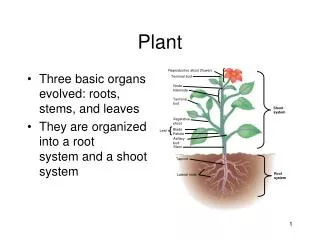
PLANT
CMD IN. INSIDE COMPUTER. A/D. RESPONSES. CONTROL ALGORITHM. +. PLANT. D/A. -. ERR. A/D. SENSORS. SENSOR FEEDBACKS.

PLANT
E N D
Presentation Transcript
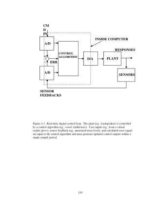
CMD IN INSIDE COMPUTER A/D RESPONSES CONTROL ALGORITHM + PLANT D/A - ERR A/D SENSORS SENSOR FEEDBACKS Figure 4.1. Real-time digital control loop. The plant (eg., loudspeaker) is controlled by a control algorithm (eg., vowel synthesizer). User inputs (eg., from a virtual reality glove), sensor feedback (eg., measured noise level), and calculated error signal are input to the control algorithm and must generate updated control outputs within a single sample period
COMPUTATION CYCLE CLOCK0 CLOCK1 CLOCK TIME ALGORITHM: (1 CLOCK) A/D PLANT SENSOR D/A Figure 4.2. Real-time control timing. For real-time digital control, the entire computation cycle must be completed in one sample period. The A/D’s provide comand and sensor inputs to the CPU on clock0. The CPU performs control calculations between clock0 and clock1. New D/A values are output to the plant on clock1.
Figure 4.3. X86 processor performance progression. The numerical processing speed of the PC CPU’s increased dramatically over the progression from 8086 to 80586 (Pentium) as both clock speed and processor efficiency improved. Column 2 is CPU clock speed, column 3 is number of clocks to perform a multiplication in the formant resonator calculation process (16 bit fixed point for the 8086 – 80286, and 64 bit floating for the rest). Column 4 is the time in microseconds to perform the multiply. Column 5 is the time to perform all the calculations for ten formant resonators. Column 5 is the percentage of a 10 kHz cycle budget (0.1 ms) consumed by calculations for 10 resonators. It is noteworthy that the transition from 16 bit integer to 64 bit floating actually resulted in less CPU time.
ALPHA REAL-TIME SYNTHESIZER FUNCTIONAL OVERVIEW 5 RESONATORS LOW PASS FILT. R2 R3 R4 R5 R1 D/A AMP SPKR IMPULSE SOURCE HARDWARE INTERRUPT TO X86 PROCESSOR CTM05 PROGRAMMABLE CLOCK Figure 4.4. Overview of the alpha real-time vowel synthesizer. This first implementation used commercially available adapter cards and prototyping circuitry external to the PC platform. It used a simple impulsive source to excite a bank of 5 second order digital resonators implemented in 16 bit scaled integer arithmetic and programmed in X86 assembly language.
CURRENT REAL-TIME SYNTHESIZER FUNCTIONAL OVERVIEW X86 INTERRUPT IMPL CLK SOURCE SELECTION 20 POLES 4 ZEROS KGLOT 88 LOW PASS FILT. . . . D/A AGC + LF1 RECORD WAV AMP GAH LF2 OUTPUT SIGNAL FILE STORE/RECALL CONTROL PARMS ASP NOISE SPKR ARB SOURCE CONTROLS ARBITRARY SOURCE FILE PARAMETER TIME VARIATION JITTER SHIMMER DIPLOPHONIA Figure 4.5. Overview of the current real-time synthesizer. Upgrades include flexible source specification (impulse, KGLOTT88, LF, or arbitrary waveform), an aspiration noise source, vocal tract transfer function numerator zeros, an automatic gain control, jitter, shimmer, diplophonia, arbitrary time variation of parameters, and the ability to store and recall time series and parameter sets. All hardware components are grouped on one adapter card.
REAL-TIME SYNTHESIZER HARDWARE CB ADDRESS BUS ADDRESS DECODE CLOCK GENERATOR AB DB CB ISA BUS TIMING & CONTROL CB DATA BUS DB ANALOG OUTPUT CONTROL BUS CB CB DB DB CONTROL REGISTER D/A LATCH D/A CONVERTER Figure 4.6. Real-time synthesizer hardware. Several hardware features were required to achieve true real-time performance on the PC platform. These include a crystal-controlled clock, a D/A converter, data latches, and timing and control glue logic to interface these components.
REAL-TIME SYNTHESIZER SOFTWARE INITIALIZATION/ SHUTDOWN INTERRUPT SERVICE START START PERORM BACKGROUND TASKS. INITIALIZE HARDWARE & PC UPDATE TIME & COUNTERS UPDATE VARIABLE CONT. PARMS INITIALIZE GRAPHIC USER INTRFC. N SHUTDOWN ? Y CALCULATE NEW OUTPUT & LATCH IT INITIATE REALTIME CONTROL STOP DISPLAY WARNING Y OVERRUN ? N KEYBRD INPUT? N RETURN Y BACKGROUND TASKS (WHILE AWAITING INTERRUPTS) DECODE & INITIATE OUTPUT TIME SERIES TO FILE LOAD PARAMETER TIME SERIES UPDATE PARMETER ETC. ... Figure 4.7. Real-time synthesizer software. Programming code may be segregated into two types: foreground (hard real-time tasks), and background (user interface, system management, etc.). The foreground tasks were performed in an ISR (interrupt service routine) and were coded in assembly language for fastest possible execution. The background tasks were coded in C language.
SOFTWARE SYNTHESIZER PROGRAM ENTRY REGENERATE ENTIRE OUTPUT TIME SERIES • SOURCE SYNTHESIS OPTIONS: • TRACK ORIGINAL PITCH • TRACK ORIGINAL POWER • APPLY RANDOM / SINUSOIDAL • TREMOR • APPLY HFPV • APPLY SHIMMER • APPLY SHAPED ASPRIATION START CREATE LF WAVE SHAPE READ PARAM & INITIALIZE CATENATE LF INTO SOURCE T.S. APPLY VOCAL TRACT FILTER REGENERATE ENTIRE OUTPUT EXECUTE KEYBOARD CMDS ADD ASPIRATION NOISE SYNTHETIC VOICE EXIT KEYBOARD INVOKED TASKS VARY LF PARAM GUI VARY FORMANT GUI GENERATE AUDIO OUTPUT SAVE/RECALL STORED PARAM SET RETURN RETURN RECOMPUTE OUTPUT RECOMPUTE OUTPUT RETURN RETURN Figure 4.8. Overview of software synthesizer operation. After invocation, the synthesizer loads parameters for the requested (previously analyzed) case and calculates the synthetic version. The program then waits for user input commands to execute functions such as modifying the LF source parameters, modifying formants, or dumping or loading time series to/from disk.
Figure 4.9a. Main GUI (graphical user interface) for the software synthesizer. Provisions are included for user specification via sliders or text of noise levels, HFPV, shimmer, etc. Options are included for tasks such as activating playback of the original or synthetic voice, turning on/off fundamental frequency/volume tracking, plotting spectra or time series, or invoking modification of LF or formants.
Figure 4.9b. LF modification GUI. This screen allows the user to control the shape of the LF source waveform by varying the LF parameters.
Figure 4.9c. Formant modification GUI. This screen allows the user to move the pole locations specifying the all-pole vocal tract model.