Integrated Electronic Window
Explore an integrated electronic window system with features like temperature sensors, H2O sensors, and motor drives to control light transmission. Learn about electrochromic windows, light sensors, and temperature sensing technology.


Integrated Electronic Window
E N D
Presentation Transcript
Integrated Electronic Window Stephen Stec Tom Ludwick Steven Silverman Betrework Tizazu Dr. NatarajanNarasimhamurthi Advisor
Project Purpose • Home Automation • ‘Neat’ Factor • Assist the aging population • Energy Reduction • Save on Heating and Cooling
Window Functionality • Provide an integrated solution for different electronic components that could be added to a home window • temperature sensor • H2O sensor (rain sensing) • motor drive (to open and close) • controlled light transmission/privacy • an intuitive user interface to control each solution • Certain systems of this window would work together to provide automated control as well.
Tint Technology Driving Electrochromic Windows
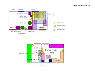
Electrochromic Windows • Chemical reaction initiated by an electric charge • Oxidation Reaction • Window Layers • Ion Storage Layer (green) • Ion Conductor Layer (yellow) • Electrochromic Layer (gray) • Reverse the polarity of the charge, reverse the direction of the reaction • This causes the window to become transparent or opaque • Reaction is very slow (~3 minutes light to dark)
Electrochromic Windows • Benefits • Low Voltage (3.3V) • Uses little or no power when reaction is complete • ~10mA @ 3.3V = 33mW • Current sense resistor to indicate when reaction has completed • Drive System • Zetex ZXMHN6A07T8 N-Channel H-Bridge • Microcontroller to control switching • Light sensors to help with tint level control
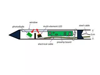
Light Sensors • LX1972 Ambient Light Detector • (instead of photo resistor) • Advantages: • Ignores both ultra violet and infrared wavelengths • Converts output current to a voltage simply by placing the LX1972 in series with a single resistor at either of its two pins • Produces a linear output • Cheaper • Disadvantage: • Available only in surface mount
Light Sensors • Closed loop system: • Outer light sensor determines the amount of light outside the window • Inner light sensor determines the present level of tint on the window • The difference between the two represents the present level of tint
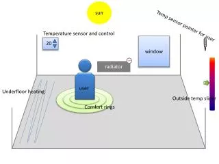
Temperature Sensors • Determines tint level in conjunction with light sensors • Placed on the inside as well as outside to measure difference (ΔT) • Cold and sunny outside-make opaque to let in warming sunlight • Hot and sunny outside-tint to keep warming sunlight out • ΔT will determine a set level of tinting
Temperature Sensing • Resistance Temperature Device (RTD) • Most stable • Most accurate • Linear relationship • Vishay Platinum SMD Chip Temperature Sensor • R0 = 500 Ω at 0˚C • Automotive, Aviation, and Industrial applications • Temperature Range: -67˚F to 311˚F (-55˚ C to 155˚C) • Only need ~ -40˚F to 150˚F (-40˚ to 66˚C) • ΔR for this range is ~250Ω (400Ω to 650Ω)
Temperature Sensor Design • Current Source to minimize error • Current-Sourcing Current Mirror • Choose Rbiaswith a low Temperature Coefficient • RTD measurements made with low source currents • 100μA to 250μA • Rbias≈ 20kΩ to 50kΩ
Temperature Sensor Calculations • ϑ = Temperature in ˚C • Ro = Resistance at 0˚C • Rϑ = Resistance at Temperature • A and B – Part specific coefficients
Window Automation Motorized Drive System
Motorized Operation • N-channel MOSFET H-bridge to control the directional rotation of the motor • Zetex ZXMHN6A07T8 • Small size • High speed switching capability • Ease of use • Contains N-channel MOSFETs on both the high side and low side • PIC will output to H-bridge closing different switches to change
Motorized Operation • Mabuchi Motor Company • RS-555PC • 24V • 4800 RPM • 1.3 A • Needed a powerful motor to move the heavy window • Attached to a worm gear using preexisting gearing from the window framing
Water Sensing • Detect H20 and send signal to microcontroller • Consists of interweaving copper tracks on a PCB board • Uses rain droplets to complete circuit • Send “rain” or “no rain” respectively • Consist of four identical sensors
Water Sensing Test • Performance Testing • 1/8’ spacing between tracks • 1/4’ spacing between tracks
Water Sensing Performance • Resistivity • Varies by track spacing • Sensitivity • Varies by track spacing • Repeatability • Consistency of Result
Water Sensing Performance Resistance (kΩ) Number of Drops
Water Sensing Performance • ¼ inch spaced copper tracks with rounded edges chosen • Its nearly as sensitive as 1/8 inch copper track • Less susceptible to false triggered positions • Repeatable and consistent
Water Sensor Design • Drop Down Resistor • Provides current path to ground • Determines Microcontroller input voltage • 1MΩresistor was chosen • After one drop of rain
Window Control Processor and User Interface
Microprocessor • Firmware in C • PIC C CCS Compiler • Microchip’s PICkit 2 Development Board • PIC16F887 • 8-bit • Each window component described above will have its own code module • This allows for parallel development
Graphical User Iterface • Runs on a personal computer. • Uses RS-232 serial communication to send commands and display current information. • Created with Microsoft Visual Studio using Visual Basic.
Graphical User Interface • Messages are one byte long with even parity. • Current baud rate is the standard 9600 bits per second. • Baud rate may be increased if transmissions take considerably more time than the rest of the PIC’s program. • Errors are more likely at higher baud rates.
User Interface Scenerio Current settings are: • Window open and unlatched • Rain sensing on and automatic tint off • Tint level 23 The operator uses the GUI to close the window and change the tint level to 15.
User Interface Response • The display sends byte 32 for closing the window and byte 15 to changing the tint level to 15. • The PIC enters an interrupt
PIC Interrupt Routine • During the interrupt, two bytes of the PIC’s memory which indicate the desired settings are updated. One byte stores the tint level and the other byte stores other settings. Desired Tint: 00010111 (23) becomes 00001111 (15) Desired other: 00001110 becomes 00000110 (open, (closed, unlatched, unlatched, rain sensing on) rain sensing on)
PIC Interrupt Routine • During the PIC’s program, the memory bytes for the desired settings are compared with two other memory bytes containing the current settings. • The PIC determines the necessary tasks. • Tasks: • Decrease Tint. • Close Window Desired tint: 00001111 (15) Desired other: 00000110 (closed, unlatched, rain sensing on) Current tint: 00010111 (23) Current other: 00001110 (open, unlatched, rain sensing on)
PIC Interrupt Routine • Whenever the tint level decreases by 1, the PIC sends the current tint level to the GUI and updates the current tint level in memory. The GUI displays the new current tint level. • When the window is done closing, the PIC sends byte 32 to the GUI and updates this current setting in memory. The GUI shows that the window is closed.
Graphical User Interface Max232 IC
Window Interface • Indicators • Buzzer • Window Automation: opening or closing • LEDs (5) • Tint Level: 0% ,25%, 50%, 75%, 100% • Controls • Pushbuttons • Select Tint Level • Window Automation
Window Interface Schematics • Don’t Use OrCad