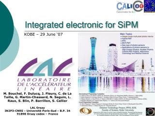
Integrated electronic for SiPM
Integrated electronic for SiPM. KOBE – 29 June ‘07. M. Bouchel, F. Dulucq, J. Fleury, C. de La Taille, G. Martin-Chassard, N. Seguin, L. Raux, S. Blin, P. Barrillon, S. Callier LAL Orsay IN2P3-CNRS – Université Paris-Sud – B.P. 34 91898 Orsay cedex – France. Introduction.

Integrated electronic for SiPM
E N D
Presentation Transcript
Integrated electronic for SiPM KOBE – 29 June ‘07 M. Bouchel, F. Dulucq, J. Fleury, C. de La Taille, G. Martin-Chassard, N. Seguin, L. Raux, S. Blin, P. Barrillon, S. Callier LAL Orsay IN2P3-CNRS – Université Paris-Sud – B.P. 34 91898 Orsay cedex – France
Introduction • LAL microelectronic group is designing integrated front-end electronic for particle physics • Its know-how has evolved from low-noise front-end to multichannel read out ASICs system on chip design allowing low-cost high number of channel read-out • That talk will introduce a bunch of Front-end ASICs designed by LAL microelectronic group • 4 ASICs suitable for SiPM read out will be presented : 2007 SPIROC 2006 HARDROC 2006 MAROC2 2004 FLC_SIPM
FLC_SIPM AHCAL TCMT 120 cm 90 cm FLC_SIPM has been designed to read out the CALICE AHCAL physics prototype It is also used in the TCMT read out ECAL beam
From Felix Sefkow’s talk Tile HCAL testbeam prototype • 1 cubic metre • 38 layers, 2cm steel plates • 8000 tiles with SiPMs • Electronics based on CALICE ECAL design, common back-end and DAQ ASICs: LAL Boards: DESY DAQ: UK DESY DESY, Hamburg U, ITEP, MEPHI, LPI (Moscow) Northern Illinois LAL, Orsay Prague UK groups Tile sizes optimized for cost reasons
Gain and dark rate uniformity correction SiPM gain varies with the high voltage value DAC to adjust gain CHANNEL BY CHANNEL from M.DanilovITEP, Moscow
Gain and dark rate uniformity correction The input DACs allow to adjust HV channel by channel via slow control on the 8000 SiPM of the detector +HV 100kΩ 8-bit DAC 100nF SiPM Preamp input 50Ω ASIC 100nF High voltage on the cable shielding
18-channel 8-bit DAC (0-5V) 18-channel front-end readout : Variable gain charge preamplifier (0.67 to 10 V/pC) Variable time constant CRRC2 shaper (12 to 180 ns) Track and hold 1 multiplexed output Power consumption : ~200mW (supply : 0-5V) Technology : AMS 0.8 m CMOS Chip area : ~10mm² Package : QFP-100 Chip description
Channel architecture for SiPM readout 40kΩ 100MΩ 0.1pF ASIC 2.4pF 8-bit DAC 0-5V 0.2pF 1.2pF 0.4pF 0.6pF 0.8pF 0.3pF in 12kΩ 4kΩ 24pF Rin = 10kΩ 10pF 50Ω 12pF 8pF 4pF 2pF 1pF 6pF 100nF 3pF • Charge Preamplifier : • Low noise : 1300e- @40ns • Variable gain : 4bits : 0.67 to 10 V/pC • CR-RC² Shaper : • Variable time constant : 4 bits (12 to 180ns) 12ns photoelectron measurement (calibration mode) 180ns Mip measurement (physic mode) compatibility with ECAL read-out
MIP and photo-electron responses • Physics mode : • Cf=0.4pF- t=180ns - Rin ON • 1 MIP = 16 p.e. injected • Vout = 23 mV @ tp = 160 ns • SLOW SHAPING FOR TRIGGER LATENCY • Calibration mode : • Cf=0.2pF - t=12ns- RinOFF • 1 SPE =0.16pC injected • (0.6mV in 270pF) • Vout = 11 mV @ tp = 35 ns
0.5% -0.5% Linearity measurement (physics mode) • Voltage swing : ~2.1V • Dynamic Range: 80 MIPs • Linearity: <1%
Cross-talk measurement Capacitive coupling contribution Non-Direct neighbouring channel x100 Channel-to-Channel cross-talk : • ~ 1-2‰ :negligible • 2 contributions : • Capacitive coupling between neighboring channels • Long distance crosstalk in all channels (comes from a reference voltage) Direct neighbouring channel x100 Sampling time Long Distance cross-talk contribution Set-up: Cf=0.4pF, t=180ns
FLC_SIPM results • Physics results on such high number of channel are coming up • So far : • Noise as expected • Coherent noise very low • Dynamic range as expected With russian SiPM With MPPC Tohru Takeshita & al Felix Sefkow & al
MAROC : a versatile front-end chip MAROC has been designed to read out 64-anode MA-PMT from HAMAMATSU. The first application is the ATLAS luminometer. Many other application have popped up (medical imaging, astrophysics, basically everything using MA-PMT)
MAROC : main features • 64 Channels – designed to read out MA-PMT • Discrimination on each channel (3 thresholds) • Multi-gain preamp (0-4, 6 bits) tunable channel by channel to correct PMT gain non uniformity • Charge measurement and 12 bit multi-channel ADC working aside and independently of threshold detection (for cross measurement or calibration) • Perfectly suitable for SIPM read-out ATLAS luminometer using Hamamatsu MA-PMT Example of high integration
MAROC block diagram Hold signal 1 Hold signal 2 Multiplexed Analog charge output Variable Slow Shaper 20-100 ns S&H 1 MUX Photons S&H 2 64 Wilkinson 12 bit ADC Multiplexed Digital charge output 64 inputs Variable Gain Preamp. Bipolar Fast Shaper Photomultiplier 64 channels EN_serializer Or 64 SiPM FS choice 64 trigger outputs Unipolar Fast Shaper Gain correction 64*6bits Cmd_LUCID 80 MHz encoder LUCID 3 discri thresholds (3*12 bits) 3 DACs 12 bits LUCID 9 Sums SUM of 7 fibres Consumption : 130mW (~2mW/channel)
MAROC measurements Channel dispersion without any correction
Trigger efficiency : minimal injection The minimum input charge is 10 fC
DAC resolution All three DAC embedded have roughly the same response, DAC2 is presented here
shaper transient response The slow shaper transient response is presented here for different preamp gains
S-curves with threshold sweep An example of trigger adjustment through the threshold (DAC step: 10) DAC1 = 800 DAC1 = 1400
50% efficiency charge vs threshold Charge threshold increases linearly with the DAC value
HARDROC presentation HARDROC has been designed to read out the CALICE RPC DHCAL technical prototype.
HARDROC main features • Full power pulsing • Digital memory: Data saved during bunch train. • Only one serial output @ 1 or 5MHz • Store all channels and BCID for every hit. Depth = 128 bits • Data format : 128(depth)*[2bit*64ch+24bit(BCID)+8bit(Header)] = 20kbits • BASICALLY : MAROC with internal RAM and time counting
One HaRD_ROC event • Depht is 128 Discris results – 64*2 bit BCID – 24 bit Chip ID - 8 bit Time Position Energy 160 bits / chip event
Auto trigger and data output Auto trigger with 10fC: Qinj=10fC in Ch7 DAC0 and DAC1=255 (~5fC) Ch7 BCID Header
Second generation chip for SiPM : SPIROC SPIROC has been designed to read out the CALICE AHCAL technical prototype
From Felix Sefkow’s talk Technical prototype architecture ~ 2000 tiles/layer LDA (Module concentrator, Optical link) • Very similar to SiW ECAL • Following CALICE / EUDET DAQ concept SPIROC 2nd gen ASIC incl ADC DIF (Layer Concentrator, Clock, control, Configuration) 2.2m With 40 µW / ch Temp gradient 0.3 K / 2m Layer units (assembly) subdivided into smaller PCBs HBUs:Typically 12*12 tiles, 4 ASICs
From Felix Sefkow’s talk Reflector Foil 100µm Polyimide Foil 100µm HBU Interface 500µm gap ASIC TQFP-100 1mm high PCB 800µm Sector wall Top Plate 600µm steel Spacer 1.7mm Top Plate fixing Component Area: 900µm high HBU height: 6.1mm (4.9mm without covers => absorber) MGPD Bolt with inner M3 thread welded to bottom plate Bottom Plate 600µm Tile 3mm Absorber Plates (steel) Integrated layer design DESY integrated
SPIROC presentation • 36-channel readout chip • Self triggered • Energy measurement : • 2 gains / 12 bit ADC 1 pe 2000 pe • Variable shaping time from 50ns to 100ns • pe/noise ratio : 11 • Time measurement : • 1 TDC (12 bits) step~100 ps – accuracy ~1ns • pe/noise ratio on trigger channel : 24 • Fast shaper : ~15ns • Auto-Trigger on ½ pe • Internal input 8-bit DAC (0-5V) for SiPM gain adjustment It is a System on chip device, including control and communication features
Block scheme of SPIROC Analog channel Analog mem. 36-channel 12 bit Wilkinson ADC for charge and time Meas. Event builder Main Memory SRAM Ch. 0 Analog channel Analog mem. Ch. 1 HCAL SLAB Analog channel Analog mem. Ch. 35 12-bit counter Time digital mem. Bunch crossing Com module Trigger control Memory pointer
Time considerations Time between two trains: 200ms (5 Hz) time Time between two bunch crossing: 337 ns Train length 2820 bunch X (950 us) A/D conv. DAQ IDLE MODE Acquisition 1ms (.5%) .5ms (.25%) .5ms (.25%) 199ms (99%) 99% duty cycle 1% duty cycle
SPIROC running modes A/D conversion Acquisition DAQ • When an event occur : • Charge is stored in analogue memory • Time is stored in digital (coarse) and analogue (fine) memory • Trigger is automatically rearmed at next coarse time flag (bunch crossing ID) • Depht of memory is 16 The events stored in the RAM are outputted through a serial link when the chip gets the token allowing the data transmission. When the transmission is done, the token is transferred to the next chip. 256 chips can be read out through one serial link • The data (charge and time) stored in the analogue memory are sequentially converted in digital and stored in a SRAM. • An event in RAM is : • The coarse time • The fine time • The charge • The shaper gain • The status of the trigger
Read out : token ring, zero suppress 1 event 5 events 3 events 0 event 0 event Chip 0 Chip 1 Chip 2 Chip 3 Chip 4 Data bus Chip 0 A/D conv. DAQ IDLE MODE Acquisition Chip 1 A/D conv. IDLE DAQ IDLE MODE Acquisition Chip 2 A/D conv. IDLE IDLE MODE Acquisition Chip 3 A/D conv. IDLE IDLE MODE Acquisition Chip 4 A/D conv. IDLE DAQ IDLE MODE Acquisition Read out of millions of channels for ILC
0.1pF-1.5pF 5pF Slow Shaper Analog memory 50 -100ns Low gain Preamplifier Q Gain selection Depth 16 Slow Shaper IN test 0.1pF-1.5pF 12-bit Wilkinson ADC Charge measurement 50pF 50-100ns Depth 16 READ HOLD IN High gain Preamplifier Fast Shaper Variable delay 15ns Discri Trigger 8-bit DAC 0-5V Depth 16 T 8-bit threshold adjustment DAC output Time measurement Common to the 36 channels Fast ramp 300ns Reference voltage SPIROC: One channel schematic
ValidHoldAnalogb gain gain Wilkinson ADC Discri output Wilkinson ADC Discri output Trigger discri Output Trigger discri Output Conversion ADC + Writing RAM RAM 16 RazRangN Chipsat 16 ReadMesureb 16 Acquisition NoTrig ExtSigmaTM (OR36) StartAcqt SlowClock Hit channel register 16 x 36 x 1 bits TM (Discri trigger) BCID 16 x 8 bits 36 Channel 0 StartConvDAQb 36 ValGain (low gain or high Gain) TransmitOn readout RamFull OutSerie 36 EndReadOut EndRamp (Discri ADC Wilkinson) StartReadOut Rstb FlagTDC Channel 1 Clk40MHz ..… ADC ramp Startrampb (wilkinson ramp) OR36 … StartRampTDC TDC ramp ChipID Chip ID register 8 bits 8 ValDimGray DAQ ASIC ValDimGray 12 bits 12
SPIROC : Photoelectron response simulation Simulation obtained with SiPM gain = 106 _ 1 pe = 160 fC High gain Preamplifier response Low gain Preamplifier response Fast shaper Tp=15ns Noise/pe ratio = 25 120mV/pe High gain Slow shaper 10mV/pe Tp=50ns Noise/pe ratio = 11 Low gain Slow shaper Tp=50ns 1mV/pe Noise/pe ratio = 3
Conclusion • Our group is able to provide in short terms integrated electronic to read out MA-PMT, SiPM or APDs. The versatility of our chips – using programmable parameters (gain, peaking time, thresholds) make them suitable for many applications • Integrated electronic is the best way to read out high number of channels detectors, it allows to reduce cost and improve compacity in every application More information : fleury@lal.in2p3.fr