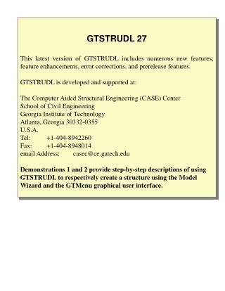
GTSTRUDL Version 27
GTSTRUDL Version 27 This latest version of GTSTRUDL includes numerous new features, feature enhancements, error corrections, and prerelease features. GTSTRUDL is developed and supported at: The Computer Aided Structural Engineering (CASE) Center School of Civil Engineering

GTSTRUDL Version 27
E N D
Presentation Transcript
GTSTRUDL Version 27 This latest version of GTSTRUDL includes numerous new features, feature enhancements, error corrections, and prerelease features. GTSTRUDL is developed and supported at: The Computer Aided Structural Engineering (CASE) Center School of Civil Engineering Georgia Institute of Technology Atlanta, Georgia 30332-0355 U.S.A. Tel: +1-404-8942260 Fax: +1-404-8948014 email Address: casec@ce.gatech.edu Demonstrations 1 and 2 provide step-by-step descriptions of using GTSTRUDL to respectively create a structure using the Model Wizard and the GTMenu graphical user interface.
GTSTRUDL 27 DEMONSTRATION 2 1. This Demonstration 2 Slide Show demonstrates the use of the GTMenu graphical user interface to create a simple Plane Truss structure, and then using GTMenu to display the structure and analysis results. 2. The slides in this Demonstration Slide Show are advanced by clicking the left mouse button, or by using the Down/Up Arrow keys, or by clicking the PgDn/PgUp (page down/up) keys. 3. The Slide Show may be exited by clicking the right mouse button 4. Since GTMenu will occupy the full screen, the Tutorial Slide Show screen can be displayed alternately with the GTMenu screen by clicking the Alt - Tab keys at the same time.
Plane Truss Structure of Demonstration 2 • Material Steel • Member PropertiesLoads • MembersAX (cm2) 1 = Self Weight • 2 = Applied Joint Loads • 1 - 4 600 11 = 1 + 2 (Gravity Load) • 6, 7 900 • 5, 8 700
Initiating GTSTRUDL 27 GTSTRUDL may be initiated from the Start menu by clicking Start - Programs - GTSTRUDL 27 - GTSTRUDL 27 as follows:
Starting GTSTRUDL Directly in GTMenu When GTSTRUDL is initiated, this GT STRUDL StartupWizard opening dialog will appear with the default working directory in the Working Directory Dialog Area. The working directory may be changed if desired (e.g., D:\Userdir). Click the GTMenu option, and then click the OK button which opens the main GT STRUDL output window , and then opens the GTMenu graphical user interface.
Select the Units-Length-Meters menu option to change the length unit to Meters.
Select the Units-Force-Mtons menu option to change the force unit to Metric Tons (Mtons).
Creating the Structural Model Beginning with Joint Coordinates Select the Create-Joints-Only menu option. The GTMenu Structural Modeling Tool menu will appear.
Select Input Coordinates to permit the input of the coordinates of joints.
In the Input Coordinates data entry box, and for each joint in sequence, enter the coordinates in the Enter Coordinates data box followed by the Enter key as follows: • Joint 1, type: 0.0 0.0 • Joint 2, type: 0.0 5.0 • Joint 3, type: 5.0 0.0 • Joint 4, type: 5.0 5.0 • Joint 5, type: 11.0 0.0 • Click the Store button at the lower right of the Input Coordinates dialog box. This will store the five input joints.
Click the Redraw button in the upper menu bar to redraw the five joints on the screen in a scale where all five joints will be visible.
Create Member Incidences and Assign Material Properties Select the Create-Members Only menu option in order to specify the incidences of the truss members.
In the Create Members dialog box, select the Material Group Assignment.
In the Material Properties dialog box, select Steel, and then click the Done box.
In the Create Members dialog box, while the Current Material Properties is set to Steel, select: • Plane Truss (the XY Global plane is the default plane), • Define Start & End, and • Generate Members. • The cursor will appear and it is then used to define the incidences of each of the eight plane truss members as described below.
Place the cursor on joint 1 and click the left mouse button. Drag the cursor to joint 2 and click the left mouse button which creates Member 1.
Place the cursor on joint 3 and click the left mouse button. Drag the cursor to joint 4 and click the left mouse button which creates Member 2. Place the cursor on joint 1 and click the left mouse button. Drag the cursor to joint 3 and click the left mouse button which creates Member 3. Place the cursor on joint 2 and click the left mouse button. Drag the cursor to joint 4 and click the left mouse button which creates Member 4. Place the cursor on joint 3 and click the left mouse button. Drag the cursor to joint 5 and click the left mouse button which creates Member 5.
Place the cursor on joint 3 and click the left mouse button. Drag the cursor to joint 2 and click the left mouse button which creates Member 6. Place the cursor on joint 1 and click the left mouse button. Drag the cursor to joint 4 and click the left mouse button which creates Member 7. Place the cursor on joint 5 and click the left mouse button. Drag the cursor to joint 4 and click the left mouse button which creates Member 8.
Click the right mouse button to exit the cursor. The incidences of all 8 Plane Truss members have been created. Click the Store button. This will cause the 8 Plane Truss members to be stored.
Assign Member Cross-Section Properties The member cross-section area properties of the 8 Plane Truss members will be defined next. Select the Create - Material and Member Properties - Member Properties menu options.
Select the Prismatic option in the Member Properties Group dialog box. The Prismatic Properties dialog box will appear.
Select the Units-Length-Centimeters menu option to change the length unit to CM.
In the Prismatic Properties dialog box, type the property name as Prop 1, and the value of AX as 600. Click the Store New button.
In the Prismatic Properties dialog box, type the property name as Prop 2, and the value of AX as 700. Click the Store New button.
In the Prismatic Properties dialog box, type the property name as Prop 3, and the value of AX as 900. Click the Store New button.
In the Prismatic Properties dialog box, click the Done button.
Select the Edit-Joints, Members and Elements-Member Data menu options. The Edit Member Data dialog box will appear.
Select the Properties option in the Edit Member Data dialog box. The cursor will appear. Use the cursor to select members 1, 2, 3, and 4. Then click the right mouse button to exit the cursor. The Member Properties dialog box will appear.
Select the member property option called Prop 1 pris AX 600 in the Member Properties dialog box, and click the Done button. Members 1, 2, 3, and 4 will be assigned the member property group called Prop 1 (i.e., Prismatic AX = 600 cm 2).
Use the cursor to select members 5 and 8. Then click the right mouse button to exit the crsor. The Member Properties dialog box will appear. Select the member property option called Prop 2 pris AX 700 in the Member Properties dialog box, and click the Done button. Members 5 and 8 will be assigned the member property group called Prop 2 (i.e., Prismatic AX = 700 cm 2).
Use the cursor to select members 6 and 7. Then click the right mouse button to exit the crsor. The Member Properties dialog box will appear. Select the member property option called Prop 3 pris AX 900 in the Member Properties dialog box, and click the Done button. Members 5 and 8 will be assigned the member property group called Prop 3 (i.e., Prismatic AX = 900 cm 2). Click the right mouse button to exit the cursor.
Click the Right Mouse button to exit the cursor. Member properties for all eight Plane Truss members have been assigned. Click the Redraw button.
Define Support Boundary Conditions Select the Edit - Joint Data menu options. The Edit Joint Data dialog box will appear.
In the Edit Joint Data dialog box, select the Support & Release option. The cursor will appear. Use the cursor to select Joint 1. Click the Right Mouse button. The Edit Support & Release dialog box will appear.
Click the Done button, and Joint 1 is now a Fully Restrained Plane Truss support joint.
Use the cursor to select Joint 3. Click the Right Mouse button. The Edit Support & Release dialog box will appear.
Select the FX Release option. Click the Done button, and support Joint 3 is now a Horizontal Roller Truss support joint. Click the Right Mouse button.
Define Self Weight and Live Loads Select the Create - Loads - Activate Independent Load menu options. The Create Indep Load dialog box will appear.
The Self Weight (dead load) of the structure will now be defined as Loading 1: Type the load Name: “1” Type the load Description: “Self Weight” Click the Store New button.
In the Self-wt of mem dialog box, select the Negative Y Load Direction, and use the default load factor 1.00 in the -Y Direction, and click the Generate Loads button. This will cause the self weight of all Plane Truss members to be automatically calculated in GTMenu, and then each time an analysis is performed. One half of each Plane Truss member’s self weight will be applied in the negative Global Y-direction at each joint upon which the Plane Truss member is incident.
Click the Yesbutton in response to the question: “Display generated loads? A graphical display of the generated self weight will be displayed. These loads can also be displayed later by using the Display - Loads menu option. In the Gravity Loads dialog box, click the Active Load button. This will cause a return to the Create Indep Load dialog box so that another load may be defined.
The applied joint forces on the structure will now be defined as Loading 2: Type the load Name: “2” Type the load Description: “Applied Joint Loads” Click the Store New button.
Click the Generate Load button. The cursor will appear. Place the cursor on Joint 2 and click the Left Mouse button. Then place the cursor on Joint 4 and click the Left Mouse button.
Click the Right Mouse button. The Individual Joint Load Values dialog box will appear. Enter the value of FX as 5.0, and click the Done button. The concentrated joint forces of 5.0 MTONS acting on joints 2 and 4 will be displayed.
Click the Generate Load button again. The cursor will appear. Place the cursor on joint 5 and click the Left mouse button. Click the Right Mouse button. The Individual Joint Load Values dialog box will appear. Enter the value of FX as 15 and the value of FY as -10 and click the Done button. The concentrated joint forces of 15 and -10 MTONS acting on joint 5 will be displayed.
Select the Display - Loads menu options. Click the Select Load button.
Select the Load 2 Applied Joint Loads menu option. Click the Done button.