Download
1 / 34
370 likes | 1.38k Views
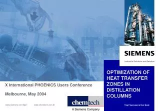
OPTIMIZATION OF A REFINERY CRUDE DISTILLATION UNIT IN THE CONTEXT OF TOTAL ENERGY REQUIREMENT. E. O. Okeke & A. A. Osakwe-Akofe NNPC R&D Division, Port Harcourt, Nigeria APACT03, York, 28 – 30, April, 2003. INTRODUCTION.

E N D
OPTIMIZATION OF A REFINERY CRUDE DISTILLATION UNIT IN THE CONTEXT OF TOTAL ENERGY REQUIREMENT E. O. Okeke & A. A. Osakwe-Akofe NNPC R&D Division, Port Harcourt, Nigeria APACT03, York, 28 – 30, April, 2003
INTRODUCTION • The Nigerian National Petroleum Corporation, has 4 refineries, in its downstream operations, • The primary goal of this refiner is to achieve and maintain high gasoline production, • Hence, the main objective of this study is to optimize gasoline production in all the refineries, • The strategy being to first target the CDUs in these refineries. Maximizing the yield of gasoline and its intermediates will directly impact positively on total pool gasoline production,
PROGRAMME FOR MAXIMIZING GASOLINE PRODUCTION • Maximizing gasoline and its intermediates production from the refinries has been planned to be accomplished in phases, viz- • Phase I – CDU 1 (the first refinery’s CDU) • Phase II – CDU 2,3,4, 5 (the other 3 refineries), • Phase III – Catalytic plants - CRU, FCC & HF Alky • Phase I began with CDU 1 as a basis to ascertain plant suitability to process different crude oil.
CDU 1 FEED & MAIN COLUMN SUBSYSTEM • The CDU 1 of the first of these refineries, the object of our presentation, was installed in the 1960s to process naphthenic crude of API 40.3 at first and another of API 35.4 afterward, • It has a main fractionator with 44 trays and 4 side strippers, and a stabilizer column.
CDU 1 DISTILLATES • The intermediate distillates are as in conventional CDUs, • Unstabilized gasoline from the main fractionator is further processed in the stabilizer column, • Straight run naphtha and other distillates from the main fractionator are routed further downstream for processing and upgrading, • Stabilizer produces an intermediate gasoline as bottoms and LPG as overhead
CDU 1 MAIN DESIGN & HARDWARE FEATURES • Licensed by SHELL and designed as a conventional crude distillation unit, • Crude oil characteristics and product requirements as applicable in establishing hardware design, • Hardware performance evaluation, maintenance and upgrading of facility undertaken periodically.
MAIN FOCUS AREAS TO ACHIEVE MAXIMUM GASOLINE IN CDU 1 Main areas are: • efficient operation of the CDU, • review of configuration of CDU to determine opportunity for further increase in gasoline yield,
GENERALIZED STRUCTURE OF THE CDU 1 The CDU can be decomposed in stages as follows: • Stage 1, the main fractionator producing feed for Stage 2 (i.e. the stabilizer) • Achievement and sustenance of increase yield must be progressive – from Stage 1 through Stage 2
METHODOLOGY – STEADY STATE SIMULATION TO OPTIMIZATION The main stages are as follows: • Compare the crude assays for the two naphthenic crudes, • Configure, specification and steady state simulation of the CDU using HYSYS.Plant, • Match HYSYS.Plant simulation results with original design requirements, • Carry out optimization of the CDU Results obtained showed good opportunity.
INCREASING GASOLINE YIELD For a given CDU, yield of gasoline derivatives depends on, • Feed characteristics, • Process requirements/operating conditions. From the above therefore, since feed is constant, optimizing gasoline yield will depend on process requirements/operating conditions.
FRONT-END CDU 1 EVALUATION FOR HYSYS IMPLEMENTATION The evaluation of the CDU is as follows: • Establish a reliable CDU configuration, determine process conditions using HYSYS and match these with the original plant design basis and requirements, • Properly decompose the structure of the CDU and determine boundary conditions for optimization, • Achieve a reliable process optimization in the context of total energy requirements.
OPTIMIZATION PARAMETERS The parameters for optimization are derived from process/hardware environments, viz, • The main fractionator and the stabilizer are linked together: stabilizer feed comes from the main fractionator, • The other gasoline blending stock, SRN, a derivative from the main fractionator is routed for further processing, • Four side strippers in the main fractionator, • The stabilizer has a condenser and a reboiler
HEAT LOAD DISTRIBUTION • CDU has an integrated heat exchanger network for heat recovery which shares loads, viz, Q1,…,Q7, where Q4 and Q5 are utilities, • Heat loads in the network are assumed to be efficiently shared, • Heat supplied through the crude charge and for the various steam stripping supplies are constant.
MODELLING PROCEDURE Stage-wise approach was adopted, viz, • Evaluate CDU configuration and steady state simulation data to determine opportunity for optimization, • Based on the structure of CDU process and hardware requirements, evolve an optimization algorithm and define boundary conditions to be solved by HYSYS.Plant, • Define steady state parameters from HYSYS.Plant simulation as first level data, and referenced as base or design values, • Optimize the overall gasoline yield in the context of total energy requirement.
OPPORTUNITIES FOR OPTIMIZING GASOLINE YIELD We observed the following: • The columns are linked in sequential arrangement, • Possibility of enhanced recoveries of gasoline in the nearest distillates below and above SRG, ie SRK and LPG, and in the stabilizer overhead, • To maintain high quality gasoline to meet base or design specification, the path to solution must be constrained, • Problem is non-linear. • Based on these conditions an algorithm was developed
THE ALGORITHM – Heat Loads • Heat load differential at steady state – • Qibase = Q1base + Q2base + …+ Q7base 1 • Heat load at any level of optimization– • Qiopt = Q1opt + Q2opt + …+ Q7opt 2 • And the differential – • Qdifferential = Qiopt - Qibase 3
THE ALGORITHM – Gasoline Yields • Gasoline yield at steady state– • yibase = y1base + y2base + …+ y7base 4 • Gasoline yield at any level of optimization • yiopt = y1opt + y2opt + …+ y7opt 5 • And the differential– • ydifferential = yiopt + yibase 6
THE ALGORITHM – Objective Function • Incorporating the various energy and gasoline costs, the resultant differential becomes, • INB = y*differential - Q*differential 7 • The objective function becomes – • Max [f(X1,X2,X3) = y*differential-Q*differential] 8 • Where, • y*differential & Q*differential are gasoline and energy costs, • X1, main column naphtha stripper reboiler return temp, • X2, main column kero stripper reboiler return temp, • X3, stabilizer reboiler return temp, • Subject to RON and RVP of gasoline being within base or design values.
HYSYS OPTMIZER • Primary variables (X1, X2, X3) are manipulated to maximize INB. Primary variables must have upper & lower limits, and these are used to normalize the primary variables, viz, • Xinorm = [(Xi – Xilower)/(Xiupper – Xilower)]. Where Xi = X1, X2, X3 • Objective function as defined by INB, • Constraints as defined for RON & RVP,
OPTIMIZATION BY SEQUENTIAL QUADRATIC PROGRAMMING • Sequential Quadratic Programming (SQP) was applied for solution. • SQP minimizes a quadratic approximation of the Lagrangian function subject to linear approximations of the constraints. The second derivative matrix of the Lagrangian function is estimated automatically. A line search procedure utilizing the watchdog technique (Chamberlain & Powel) is used.
PROBLEM SOLUTION • Sequential quadratic programming was found to be ideal for solution, • Solution was found for all cases studied, • General increase in yield of stabilizer feed and SRN from the main column, • Gasoline yield was increased by 8 %
TESTING ALGORITHM ROBUSTNESS & RELATIONSHIP OF KEY PARAMETERS Some optimization test runs were done using same HYSYS.Plant to • Test the robustness and reliability of the algorithm at achieving early convergence, • Determine the variation of key parameters, that impact on the structure of the CDU and the interaction of the main fractionator and the stabilizer. These parameters are the naphtha stripper reboiler return temp, the kero stripper reboiler return temp, and the stabilizer gasoline.
VARIATION OF GASOLINE WITH NAPHTHA STRIPPER REBOILER RETURN TEMP
VARIATION OF GASOLINE WITH KERO STRIPPER REBOILER RETRUN TEMP
OBSERVATIONS FROM THE OPTIMIZATION • The optimization based on this algorithm achieves early convergence, • As expected, the naphtha stripper (X1) and kero stripper reboiler (X2) temperatures have indirect impact on the stabilizer gasoline, while the stabilizer reboiler (X3) temperature has a direct impact on the same gasoline yield, • The 3 parameters – X1, X2 & X3 are manipulated as appropriate to optimize the gasoline produced.
CONCLUSION • Sequential quadratic programme technique ideal for solution, • Solution ofthe algorithm is reliable, achieving early convergence in the cases studied, • Objective of obtaining increased gasoline yield in the context of reduced energy requirement achieved, • Since the configuration of the refinery CDUs are similar, this algorithm can be applied to optimize the CDU 2,3,4,5 in the other 3 refineries