Download
1 / 24
240 likes | 475 Views
Geologic Storage of CO 2. Next Generation Coal Howard Herzog MIT Laboratory for Energy and Environment October 6, 2005. IPCC Special Report. Intergovernmental Panel on Climate Change (IPCC) Working Group III Special Report on Carbon Dioxide Capture and Storage Accepted September 26, 2005

E N D
Geologic Storage of CO2 Next Generation Coal Howard Herzog MIT Laboratory for Energy and Environment October 6, 2005
IPCC Special Report • Intergovernmental Panel on Climate Change (IPCC) • Working Group III • Special Report on Carbon Dioxide Capture and Storage • Accepted September 26, 2005 • Summary for Policymakers on-line at www.ipcc.ch Howard Herzog / MIT Laboratory for Energy and the Environment
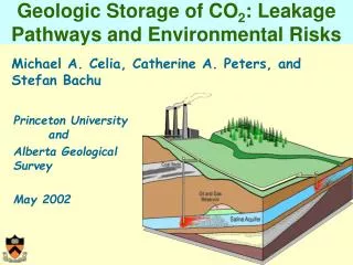
IPCC Special ReportOverview Storage of CO2 in deep, onshore or offshore, geological formations uses many of the same technologies that have been developed by the oil and gas industry and has been proven to be economically feasible under specific conditions for oil and gas fields and saline formations, but not yet for storage in unminable coal beds. Howard Herzog / MIT Laboratory for Energy and the Environment
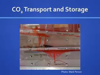
Carbon dioxide can be stored in several geological targets, usually as a supercritical phase Howard Herzog / MIT Laboratory for Energy and the Environment
Experience and Evolution from Oil & Gas Operations • Acid Gas Injection • Enhanced Oil Recovery (EOR) • Natural Gas Storage • CO2 Transport Howard Herzog / MIT Laboratory for Energy and the Environment
Acid Gas Injection • First began: Acheson Field, 1989 • In 2001, nearly 6.5 Billion cubic feet (360,000 tonnes) of acid gas injected at > 30 locations. • Between 50 thousand and 5 million scf per day. Compositions vary but many over 90% CO2. • Largest: Westcoast Energy injects 28 million scf per day (Sleipner: 50 million scf of CO2 per day) Acid Gas Disposal sites in Alberta, Canada. Map provided by Nickle’s New Technology Magazine, September 13, 2002 Howard Herzog / MIT Laboratory for Energy and the Environment
Enhanced Oil Recovery • First began: Scurry County, Texas, 1972 • In 2000, 84 commercial or research-level CO2-EOR projects operational worldwide (72 in US) • Rangely Field (Colorado) • Started CO2 injection in 1986 • 346 producers, 235 injectors • Injection rate of about 150 million scf/day (8300 t/d) • Estimated leak rate of <170 tons/yr out of 23 million tonnes purchased (<0.001%/yr) • Source: Applied Geochemistry, vol. 18, pp.1825-1838 (2003). Howard Herzog / MIT Laboratory for Energy and the Environment
Natural Gas Storage • First began: 1915 in a partially depleted gas field. • Total storage 1955: 2.1 Tcf • Total storage 1985: 8 Tcf • Volume of 8 Tcf will store one year of all US power plant CO2 emissions • Since 1980’s, storage capacity has stabilized at around 8 Tcf while capacity to deliver has increased • Total US consumption 2000 > 22 Tcf Natural Gas Storage by Type available at http://www.fetc.doe.gov/scng/trans-dist/ngs/storage-ov.html Howard Herzog / MIT Laboratory for Energy and the Environment
CO2 Transport • Extensive network of CO2 pipeline stretching nearly 2000 miles, mostly in the United States • 49CFR195 addresses transport of hazardous liquids and CO2 • CO2 pipelines classified as High Volatile Low Hazard and Low Risk. • Canyon Reef Carriers (CRC) pipeline, 1972 • Relatively few failures (with no injuries) • Extends 140 miles from McCarney, Texas, to Kinder Morgan’s SACROC field • Size: 16 inches in diameter with capacity to deliver up to 240 MMscf of CO2 per day Howard Herzog / MIT Laboratory for Energy and the Environment
IPCC Special ReportOverview Storage of CO2 in deep, onshore or offshore, geological formations uses many of the same technologies that have been developed by the oil and gas industry and has been proven to be economically feasible under specific conditions for oil and gas fields and saline formations, but not yet for storage in unminable coal beds. … Three industrial-scale storage projects are in operation: the Sleipner project in an offshore saline formation in Norway, the Weyburn EOR project in Canada, and the In Salah project in a gas field in Algeria. Others are planned. Howard Herzog / MIT Laboratory for Energy and the Environment
CO2 Injection ProjectsMillion Tonne per Year Scale Howard Herzog / MIT Laboratory for Energy and the Environment
IPCC Special ReportCapacity Available evidence suggests that worldwide, it is likely that there is a technical potential of at least about 2,000 GtCO2 (545 GtC) of storage capacity in geological formations. There could be a much larger potential for geological storage in saline formations, but the upper limit estimates are uncertain due to lack of information and an agreed methodology. The capacity of oil and gas reservoirs is better known. Technical storage capacity in coal beds is much smaller and less well known. Howard Herzog / MIT Laboratory for Energy and the Environment
Site Selection • Reservoir Characteristics • Injectivity • Accessible pore volume • Containment • Reachable from CO2 Source Howard Herzog / MIT Laboratory for Energy and the Environment
IPCC Special ReportRegulation Some regulations for operations in the subsurface exist that may be relevant or in some cases directly applicable to geological storage, but few countries have specifically developed legal or regulatory frameworks for long-term CO2 storage. Existing laws and regulations regarding inter alia mining, oil and gas operations, pollution control, waste disposal, drinking water, treatment of high-pressure gases, and subsurface property rights may be relevant to geological CO2 storage. Long-term liability issues associated with the leakage of CO2 to the atmosphere and local environmental impacts are generally unresolved. Some States take on long-term responsibility in situations comparable to CO2 storage, such as underground mining operations. Howard Herzog / MIT Laboratory for Energy and the Environment
Permitting - Current • EPA Underground Injection Control (UIC) Program • Created under the Safe Drinking Water Act (1974) • Almost all underground injections must be authorized by permit • Exemption for natural gas storage • States may receive primacy for permitting – some states currently do allow injection into deep saline aquifers • Five classes of UIC injection wells • Relaxed standards for injection wells related to enhanced oil recovery (CO2-EOR) • No class specific to carbon sequestration • Pilot projects have been permitted under the Class V experimental well category Howard Herzog / MIT Laboratory for Energy and the Environment
Measurement, Monitoring, and Verification • Role of MMV • Understand key features, effects, & processes • Injection management • Delineate and identify leakage risk and leakage • Provide early warnings of failure • Verify storage for accounting and crediting • Currently, there are abundant viable tools and methods, but MMV systems still need to be developed Howard Herzog / MIT Laboratory for Energy and the Environment
IPCC Special ReportLeakage Observations from engineered and natural analogues as well as models suggest that the fraction retained in appropriately selected and managed geological reservoirs is very likely to exceed 99% over 100 years, and is likely to exceed 99% over 1,000 years. For well-selected, designed and managed geological storage sites, the vast majority of the CO2 will gradually be immobilized by various trapping mechanisms and, in that case, could be retained for up to millions of years. Because of these mechanisms, storage could become more secure over longer timeframes. Howard Herzog / MIT Laboratory for Energy and the Environment
Storage Mechanisms • Physical trapping • Impermeable cap rock • Either geometric or hydrodynamic stability • Residual phase trapping • Capillary forces immobilized fluids • Sensitive to pore geometry (<25% pore vol.) • Solution/Mineral Trapping • Slow kinetics • High permanence • Gas adsorption • For organic minerals only (coals, oil shales) Howard Herzog / MIT Laboratory for Energy and the Environment
Leakage • Some leakage is inevitable – question is whether the leakage will have any impacts on HSE or climate (there is active debate on value of temporary storage) • Pathways • Well integrity (cement damage) • Fracturing • Faulting • Permeation and Spillover • Leakage rate not a simple logistic function (i.e., x% per year) Howard Herzog / MIT Laboratory for Energy and the Environment
IPCC Special ReportRisks With appropriate site selection informed by available subsurface information, a monitoring program to detect problems, a regulatory system, and the appropriate use of remediation methods to stop or control CO2 releases if they arise, the local health, safety and environment risks of geological storage would be comparable to risks of current activities such as natural gas storage, EOR, and deep underground disposal of acid gas. … Impacts of elevated CO2 concentrations in the shallow subsurface could include lethal effects on plants and subsoil animals, and contamination of groundwater. High fluxes in conjunction with stable atmospheric conditions could lead to local high CO2 concentrations in the air that could harm animals or people. Pressure build-up caused by CO2 injection could trigger small seismic events. Howard Herzog / MIT Laboratory for Energy and the Environment
Types of Risk • Operational Risks • Managed today • Climate Risks • Liability that can be handled • In Situ Risks • Formation leaks to the surface • Migration within formation • Seismic events Howard Herzog / MIT Laboratory for Energy and the Environment
IPCC Special ReportAccounting The current IPCC Guidelines do not include methods specific to estimating emissions associated with CCS. The general guidance provided by the IPCC can be applied to CCS. A few countries currently do so, in combination with their national methods for estimating emissions. The IPCC guidelines themselves do not yet provide specific methods for estimating emissions associated with CCS. These are expected to be provided in the 2006 IPCC Guidelines for National Greenhouse Gas Inventories… Howard Herzog / MIT Laboratory for Energy and the Environment
Geological StorageGeneral Conclusions • Practical issues • CO2 transport, injection and storage has been occurring since the early 1970’s. Tens of millions of tons of CO2 are injected annually. • Further scale up would be required to play significant role in US power sector CO2 abatement. All key technologies and practices are in current commercial operation. No “breakthrough” technological innovations appear necessary for this scale-up. • Volume of the total annual US power sector CO2 emissions are in the same order of magnitude volume of other key US gas and fluids currently injected and stored underground (e.g., natural gas, wastewater in Florida, oilfield brines) • Environmental issues • Based on our study of analogues, short term (three-decade) and local environmental risks are well understood and can be managed by current industry best practices. • Long term (beyond three decade) risks are by definition uncertain but no evidence to date suggests significant leakage. • Best near term course of action is to conduct pilot projects to gather information that will allow us to address the issue of long term risks and uncertainties. Howard Herzog / MIT Laboratory for Energy and the Environment
Contact Information Howard Herzog MIT Laboratory for Energy and the Environment (LFEE) Room E40-447 Phone: 617-253-0688 E-mail: hjherzog@mit.edu Web Site: sequestration.mit.edu Howard Herzog / MIT Laboratory for Energy and the Environment