Download
1 / 11
110 likes | 260 Views
Scanners – Robots – Measurement Plans Synergy in Motion. Peter Howard Jack Shry. Bruce Thomas Joe Calkins Robert Salerno, Ph.D. Scott Sandwith. Motivation Metrology Solution. Lidar Scanner Target-less Technology Feature based measurements

E N D
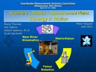
Scanners – Robots – Measurement Plans Synergy in Motion Peter Howard Jack Shry Bruce Thomas Joe Calkins Robert Salerno, Ph.D. Scott Sandwith
Motivation Metrology Solution • Lidar Scanner • Target-less Technology Feature based measurements • Ideal for unattended and automatic inspection • Need to automatically reposition to scan entire object (ex: Car) • Metrology software system architecture required to integrate the measurement system, CAD design, and robotic manipulator • Measurement Plan capability required to automatically acquire and analyze the data • It’s Cool !!
Component 1: Lidar Scanner • Simple Automation: Programmable part and tool feature inspections, alignments, reports, initiate programs remotely • Accuracy: 65 mm at 10 m • Surface/Feature Measurements: • MV200 requires only 1 pico-watt (10-12W) of return signal any surface • Fast: 1,000 measurements per second • Versatile: Used in varied configurations • Portable independent measurement system • Part of an automated robotic metrology system • Non-contact Target-less Features • No Photogrammetry Dots • No Laser Tracker SMRs • No Retro Reflectors • No Probes • No Contact
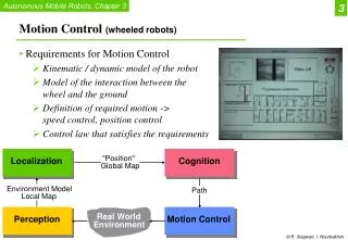
Component 2: Robot • Reliable Robot for handling • Long reach • 2.1 times more with Flip Over Mechanism • Variety of layouts • A simple motor direct drive mechanism • Minimizes the interference area • Small/slim wrist allows the robot to operate in a small space
Component 3: Integration Software • Programmable measurement planning with dynamic real time graphical interface • Distributed computing capable (real-time multi-task measurement and analysis across multiple computers) • Instrument compensation • Synchronous Measurement between Instruments (Master-Slave or Synchronous Polled Modes) • TCP/IP interfaces to instruments to enable distributed processing • Supports remote process control and monitoring. • Common instrument user-interface
System Integration • One interface controls and coordinates the system components • Extrinsic Calibration through In-line Robot Control Model: • Tool to CLR Frame • Robot Base to WORLD • Integrated graphical automation programming for n systems • Distributed computing • Remote monitoring and control
Benefits / Applications • Increased workspace for metrology equipment by extending visibility • Integrates reliable hybrid technologies on a common platform through general object oriented architecture • Adaptive Automation improves process reliability • If the system can’t quite see the feature it can be programmed to interactively hunt it down • Custom configurations fit the application • Robot moves instrument • Robot move the part • Adaptive control • Etc… • Integrated robot performance enhancements (feedback / calibration loop)
Questions – Future Direction What's Next?