Download
1 / 19
190 likes | 341 Views
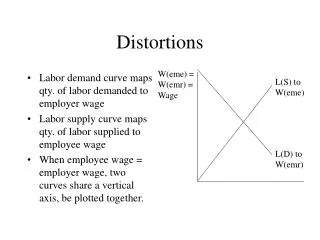
Software Development For Correction of Gradient-Nonlinearity Distortions in MR Images. T.S. Lee, K.E. Schubert Computer Science CSUSB. R.W. Schulte Radiation Medicine LLUMC. Functional Proton Radiosurgery. Functional Neurosurgery Trigeminal Neuralgia Parkinson’s Disease

E N D
Software Development For Correction of Gradient-Nonlinearity Distortions in MR Images T.S. Lee, K.E. Schubert Computer Science CSUSB R.W. Schulte Radiation Medicine LLUMC
Functional Proton Radiosurgery Functional Neurosurgery Trigeminal Neuralgia Parkinson’s Disease Brain regions (< 1 cm) Proton Radiosurgery Accurate to less than 1 mm MRI for target localization Distinguish tissue types 512512 images 262,144 pixels/study Gradient nonlinearity distortions (~2mm)
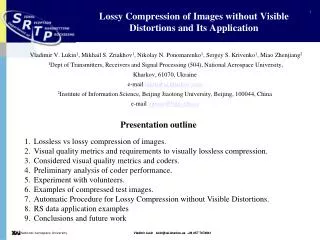
Axial Plane Example MR Phantom Images Coronal Plane Sagittal Plane
Partial Phantom Partial Phantom Bad Slides Off Center Phantom No Phantom
Can We Fix it? Air Bubble Leaky Slice
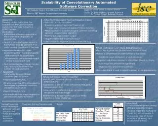
Axial Plane Coronal Plane Sagittal Plane Example Edge Images
Midplanes Stack Midpoints Fit Midplane Calculate Midpoints Ideal shape, size, and orientation of phantom’s faces
Ideal Planes Shift ±½ the phantom dimension Perpendicular to face
Distortion Modeling Magnetic Field of Cylinder Sum of spherical harmonics:
Measured Distortion Modeling Corrected
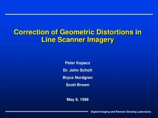
Results Theoretical undistorted points vs. corrected points Standard deviations of correction +X face: Standard Deviation = 0.23503 mm -X face: Standard Deviation = 0.25168 mm +Y face: Standard Deviation = 0.15322 mm -Y face: Standard Deviation = 0.15823 mm +Z face: Standard Deviation = 0.13548 mm -Z face: Standard Deviation = 0.14173 mm
Conclusions 3s range 0.4 – 0.8 mm 1-2 pixels on each image Originally 2mm (5-6 pixels) Accurate localization of anatomical targets
Future Work Further verification and testing Clinical trials FDA approval Treatment on humans