Download
1 / 41
470 likes | 1.01k Views
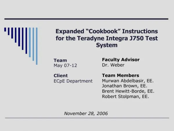
Mixed-Signal Option for the Teradyne Integra J750 Test System. May08-12 Emily Evers Vincent Tai. Problem Statement. The Teradyne system has been updated to allow for analog circuits to be tested, but there are no working test files for ADC, DAC and Op-Amps.

E N D
Mixed-Signal Option for the Teradyne Integra J750 Test System May08-12 Emily Evers Vincent Tai
Problem Statement The Teradyne system has been updated to allow for analog circuits to be tested, but there are no working test files for ADC, DAC and Op-Amps.
Concept Sketch and System Block Diagram Hardware IG-XL Software Documentation Devices Hardware Software
Devices Analog-to-Digital (ADC) Digital-to-Analog (DAC) Op-Amp Hardware Device Interface Board (DIB) Connects daughter board to tester via pogo pins Daughter Board Connects device to DIB IG-XL Software Test Plan Pin and Channel Map AC and DC Specs Timing Pattern Documentation Updated Cookbook Commented IG-XL files System Description 4
User Interface IG-XL Software Cookbook DIB Operating Environment The room environment needs to be kept at a consistent temperature of 25°C ± 3° Electrostatic discharge wrist bands must be worn when using the tester Access code User Interface and Operating Environment
Functional Cookbook be written for the new users Testing procedures covers the devices: Analog-to-Digital (ADC) Digital-to-Analog (DAC) Op-Amp Nonfunctional Documentation in English Test program for devices and similar ones Cookbook for specified devices Easy to trouble shooting Requirements
Market Survey • Teradyne website • Previous team’s website • Teradyne lab manuals
Review Status Previous work Teradyne Training Material IC Interface Daughter Board DIB Test Plan Development Create IG-XL code for testing devices Debug previous code Add current limits New test plans Execute testing Documentation Create Mixed-Signal Option Cookbook Create maps for daughter board, DIB and socket converters Reporting Work Breakdown Structure
Resource Requirements Resource Team Faculty Advisor: Dr. Weber Faculty Advisor: Dr. Smith Team effort 10
Resource Requirements Financial requirements 11
Risks • Risk: • Problems learning program • Limited team members • Risk Management: • Read Teradyne manuals and previous groups documentation • Time management
Inputs Process Outputs Parts Results Cookbook Input/Output Signals ADC DAC Op-Amp Calculations AD7892 AD7470 AD5440 AD5447 AD823 Hardware ADC & DAC Op-Amp Software Interfaces INL & DNL IG-XL Program J750 Tester DIB Daughterboard Socket converter Bandwidth Offset Voltages Intermodulation Tests Computer Design Method
Input DAC LTC1450 Op-Amp AD823 ADC AD7470 Output Input signals Output signals Calculations ADC INL and DNL DAC INL and DNL Op-Amp Offset Voltage Bandwidth Intermodulation Distortion Input and Output Specification
Hardware Daughterboard DIB Socket converter User Interface Updated Cookbook IG-XL test files Software Pattern Tool IG-XL Pin and Channel Maps AC, DC, and Global Specs Time sets and Pin Levels Test Procedures Hardware, Software, and User Interface Specification
Test Specification • Component Test • Test individual IG-XL source and capture • System Test • Test IG-XL test file and pattern
Detailed Design • DAC Schematic
Detailed Design • Op-Amp Schematic
Detailed Design • ADC Schematic
Build – Pin Map • Define pins on IG-XL
Build – Channel Map • Define connections from daughterboard to tester • DAC
Build – Channel Map • Op-Amp
Build – Channel Map • ADC
Build – AC Specs • Specify AC variables
Build – DC Specs • Specify DC variables
Build – Pin Levels • User specify voltage level for high/low logic level.
Build – Time Sets • Create timing basis for pattern • Allow for testing on digital pins
Build – Test Procedures • Set up user defined tests
Build – Test Instances • Set up IG-XL template tests • Input data for user defined tests
Build – Pattern • Uses time sets from IG-XL file • User defined inputs • Can be used to start analog and digital source and capture signals
Build – Pattern • Several sheets are used in the pattern file • Pin Lists • Imports (time sets) • Instruments
Test • System testing was done using an oscilloscope
Test • Teradyne System Testing • Functional Test • Continuity Test
Test • Functional and Continuity Outputs
Earned Value Analysis • Budgeted Cost of Work Scheduled: $4365 • Actual Cost of Work Performed: $3650 • Budgeted Cost of Work Performed: $3895 • Cost Variance: $3530 • Schedule Variance: -$470 • Cost Performance Index: 1.067 • Schedule Performance Index: 89.23%
Lessons Learned • Team Work • The value of hands-on experience • Verify Input Signals: Use oscilloscope and multimeter.
Conclusions • Accomplishments • Updated CprE 210 D-flip flop test • Created an interface mapping of the current boards • ADC • Wired daughter board • Created IG-XL test file • Ran tests
Conclusion • Accomplishments • DAC • Wired daughterboard • Created IG-XL test file • Op-Amp • Wired daughterboard • Created IG-XL test file • Updated Cookbook
Conclusions • Future Work • Run tests on DAC and Op-amp • Fix if needed • Finish ADC test file