Download
1 / 25
250 likes | 366 Views
The project aims to design a versatile device for cellular phones, enabling various applications like distress alerts, infrared alarms, and more. Using integrated technologies, the accessory offers connectivity and control options through a user-friendly interface.

E N D
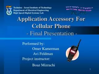
Technion – Israel Institute of Technology Department of Electrical Engineering High Speed Digital Systems Lab Application Accessory For Cellular Phone - Final Presentation - Performed by: Omer Kamerman Avi Feldman Project instructor: Boaz Mizrachi
Project Goals - Reminder • Design and implementation an independent generic device which can function as a host platform of various applications for cellular phone. • Key futures: Generic and versatile,Multi compatibility, Key ring format Using multipurpose hardware : Microcontroller, transceiver, etc. Low voltage supply I/O : Configuration via GUI , few features via a mobile phone. Communication interface- Keypad, Connectivity to PC. • Base on integral abilities can perform the subsequent applications:Distress Button, Infra red alarm system, Thermometer, Switcher
Peripheral devices Block Diagram Cellular RF CellularNetwork RS 232 Cellular Transceiver TR1000 AT Command PIC18LF4620 Thermometer TCN75 PC .NET I2C RS 232
Main Device • Features : • Connectivity via RS-232 “Nokia” data cable to Nokia cellular phone. • Connectivity via RF to peripheral devices. • On board temp. sensor. • Connectivity via RS-232 cable to a GUI application on PC.
TR1000 PIC18LF4620 DS276 LE33ABD On Board Antenna 1 Line Connector: RS-232, ICD , Vdd
Distress Button RF RS232
Antenna Test Point PIC18LF4620 TR1000 Push Button 3V Battery
Infra Red Alarm System Motion sensor RF RS232
PIC18LF4620 and TR1000 Pir Signal , 9V battery Socket Pir LM1085 – 3.3V
Thermo Meter TCN 75A I2C RS232
Relay ( Switch ) RF Relay RS232
Omron Relay 220V/16A Regulator 3.3 V 9 V and signals socket In/Out Power Socket 220V/16A Regulator 5 V Relay and Main Device
Pc Connectivity • A .NET application in windows. • The application helps the user to configure: • The SMS text format. • List of phone numbers to send SMS. • To set the incoming SMS for the Relay. • To set the temp bounds in the Thermo application.
PIR VIEW REMOTE VIEW
THERMO VIEW RELAY VIEW
Getting Power from RS-232 • Extra hardware. • Opening by software the serial Port in order to get power from RS - 232.
Hardware design Main Device: • Micro Controller – “Micro chip” PIC18LF4620 – Nano Watt Tech. QFN package. • RF – “RFM” TR1000 – Transceiver, Low Voltage and Current, OOK modulation. • Connector – “Nokia“ RS-232 data cable. • Thermometer – “Micro Chip” TCN75 – support I2C . Remote control • Micro Controller – “Micro chip” PIC18LF4620. • RF – “RFM” TR1000 – Transceiver. • Switch button.
Hardware design – cont. Pc connector: • Micro Controller – “Micro chip” PIC18LF4620. • RF – “RFM” TR1000 – Transceiver. • Regulator – LE33ABD – Very low voltage regulator. • Connector – 9 pins RS-232. Motion Sensor: • Micro Controller – “Micro chip” PIC18LF4620. • RF – “RFM” TR1000 – Transceiver. • PIR – Low Voltage sensor – 9V Battery. Switcher: • Micro Controller – “Micro chip” PIC18LF4620. • RF – “RFM” TR1000 – Transceiver. • Relay module – Omron.
Software design • One code for all devices. Must be efficient & generic. • Low power device. PIC and RF chip work (out of sleep mode) only when they need. • Preferring to use integral hardware features of the PIC like INTERRUPTS , I2C and UART. • RF code write in assembly in order to insure real time performances.
Software design – RF SW • Design as ISR - TMR0 interrupt. • Work in 4800 Hz. • Used Manchester encoding scheme – DC balanced. • Each bit map to 8-bit symbol perfect 1 - 11110000 perfect 0 – 00001111 • Sync the trigger after each bit. • Fix package length – 16 bytes (11 bytes of data). • Add preamble bits before each package. • As a result of low performances of the PIC in handle protocol with high overhead demands, work with ALOAH or S&W.
Project status & milestones. • Defining the device - features and Applications. • Studying the available Hardware and tech – Datasheet, Application notes, forums, technical sites. • Selecting the Hardware – PIC18LF4620, TR1000, TCN75, PIR, Regulators, Connectors and Plastic Box. • Hardware design – ORCAD • Hardware Layout. • Writing code for the communication interface – USART, AT Commands, I2C , RF , Interrupts - *.c & *.h & *.inc. rf_func , radioisr , i2c_func , interrupt_func , sms etc. • Writing drivers for the main and peripherals components. main , thermo , relay , pir , remote etc.
Project status & milestones. (Cont.) • Design and implementation (wire-warp) – PIC, TCN75. • Analysis of Nokia FBUS & MBUS protocols. • Checking of the received PCB from production and primal assembly check. • Hardware check , debug and fix. • RF HW & SW debug. • Finish writing drivers for the components. eeprom , config ,sms2 etc’. • Writing the User interface (GUI) - .NET. • Integration, testing and Debug of the Software & Hardware.
Project open Issues. • RF Network Stop & Wait protocol for configuration from the PC. • All Software implemented, including fragmentation. • First pack was sent from source to destination and an ACK message was received back in the source. ( The protocol tested by code and scope ) • PIC is incapable handling with the overhead of the protocol. • Nokia “Pop Port” : • All authorized “Nokia” peripheral devices has an hand shack protocol named FBUS. Once the connection is established RS-232 protocol is enabled and getting 3.3 V power is allowed by the cellular. • All the knowledge for this protocol learned. • Few tests were made to assure the protocol.
Project Celltech in numbers • Design 3 PCB. • Assembly 7 different versions of PCBs. • Hardware design include 62 different Components. • Write 3488 lines of code.