Download
1 / 45
450 likes | 570 Views
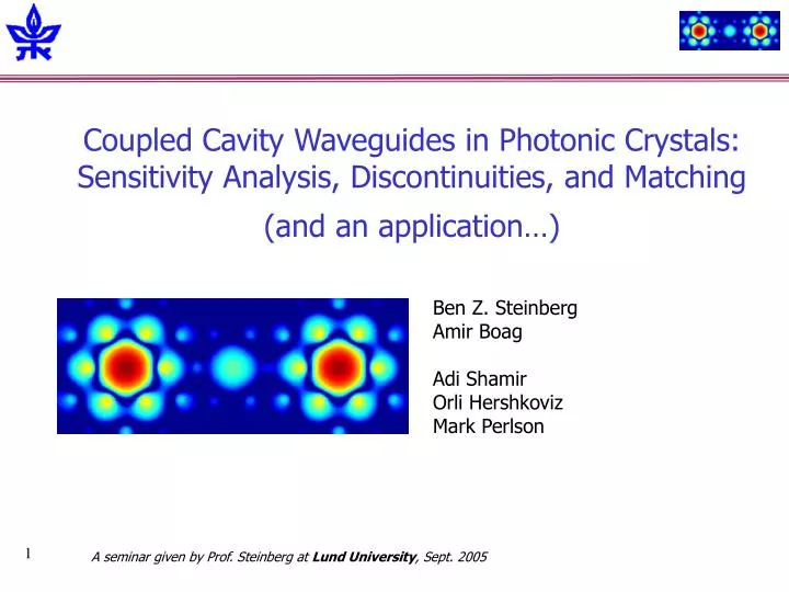
Coupled Cavity Waveguides in Photonic Crystals: Sensitivity Analysis, Discontinuities, and Matching (and an application…). Ben Z. Steinberg Amir Boag Adi Shamir Orli Hershkoviz Mark Perlson. A seminar given by Prof. Steinberg at Lund University , Sept. 2005. Presentation Outline.

E N D
Coupled Cavity Waveguides in Photonic Crystals:Sensitivity Analysis, Discontinuities, and Matching(and an application…) Ben Z. Steinberg Amir Boag Adi Shamir Orli Hershkoviz Mark Perlson A seminar given by Prof. Steinberg at Lund University, Sept. 2005
Presentation Outline • The CCW – brief overview • Disorder (non-uniformity, randomness) Sensitivity analysis [1] : • Micro-Cavity • CCW • Matching to Free Space [2] • Discontinuity between CCWs [3] • Application: • Sagnac Effect: All Optical Photonic Crystal Gyroscope [4] [1] Steinberg, Boag, Lisitsin, “Sensitivity Analysis…”, JOSA A 20, 138 (2003) [2] Steinberg, Boag, Hershkoviz, “Substructuring Approach to Optimization of Matching…”, JOSA A, submitted [3] Steinberg, Boag, “Propagation in PhC CCW with Property Discontinuity…”, JOSA B , submitted [4] B.Z. Steinberg, ‘’Rotating Photonic Crystals:…”, Phys. Rev. E, May 31 2005
The Coupled Cavity Waveguide (CCW) • A CCW (Known also as CROW): • A Photonic Crystal waveguide with pre-scribed: • Center frequency • Narrow bandwidth • Extremely slow group velocity • Applications: • Optical/Microwave routing or filtering devices • Optical delay lines • Parametric Optics • Sensors (Rotation)
Regular Photonic Crystal Waveguides Large transmission bandwidth (in filtering/routing applications, required relative BW )
The Coupled Cavity Waveguide b a2 a1 Inter-cavity spacing vector:
The Single Micro-Cavity Micro-Cavity geometry Micro-Cavity E-Field Localized FieldsLine Spectrum at
Widely spaced Micro-CavitiesLarge inter-cavity spacing preserves localized fields m1=2 m1=3
Bandwidth of Micro-Cavity Waveguides Large inter-cavity spacing weak coupling narrow bandwidth Inter-cavity coupling via tunneling: Transmission vs. wavelength Transmission bandwidth vs. inter-cavity spacing
Tight Binding Theory The single cavity modal field resonates at frequency A propagation modal solution of the form: where Insert into the variational formulation:
The result is a shift invariant equation for : Infinite Band-Diagonally dominant matrix equation: The operator , restricted to the k-th defect - Wave-number along cavity array Tight Binding Theory (Cont.) Where: It has a solution of the form:
Variational Solution w G M wc Dw M G p/|b| p/|a1| Wide spacing limit: Bandwidth: k Central frequency– by the local defect nature; Bandwidth– by the inter cavity spacing.
Center Frequency Tuning Recall that: Approach: Varying a defect parameter tuning of the cavity resonance Example: Tuning by varying posts’ radius (nearest neighbors only) Transmission vs. radius
Structure Variation and Disorder:Cavity Perturbation + Tight Binding Theories Interested in: [1] Steinberg, Boag, Lisitsin, “Sensitivity Analysis…”, JOSA A 20, 138 (2003) • Perfect micro-cavity • Perturbed micro-cavity Then (for small ) For radius variations Modes of the unperturbed structure
Disorder I: Single Cavity case Uncorrelated random variation - all posts in the crystal are varied Variance of Resonant Wavelength • Cavity perturbation theory gives: Due to localization of cavity modes – summation can be restricted to N closest neighbors • Perturbation theory: • Summation over 6 nearest neighbors • Statistics results: • Exact numerical results of 40 realizations
Disorder & Structure variation II: The CCW case Modal field of the (isolated) –th microcavity. Its resonance is • Mathematical model is based on the physical observations: • The micro-cavities are weakly coupled. • Cavity perturbation theory tells us that effect of disorder is local (since it is weighted by the localized field ) therefore: • The resonance frequency of the -th microcavity is where is a variable with the properties studied before. • Since depends essentially on the perturbations of the -th microcavity closest neighbors, can be considered as independent for . • Thus: tight binding theory can still be applied, with some generalizations
An equation for the coefficients Manifestation of structure disorder Unperturbed system • Difference equation: • In the limit (consistent with cavity perturbation theory)
Matrix Representation Eigenvalue problem for the general heterogeneous CCW (Random or deterministic): • a tridiagonal matrix of the previous form: • And: From Spectral Radius considerations: Random inaccuracy has no effect if: Canonical Independent of specific design/disorder parameters
Numerical Results – CCW with 7 cavities of perturbed microcavities of perturbed microcavities
Sensitivity to structural variation & disorder In the single micro-cavity the frequency standard deviation is proportional to geometry / standard deviation In a complete CCW there is a threshold type behavior - if the frequency of one of the cavities exceeds the boundaries of the perfect CCW, the device “collapses”
Substructuring Approach to Optimization of Matching Structures for Photonic Crystal Waveguides • Matching configuration • Computational aspects – numerical model • Results [2] Steinberg, Boag, Hershkoviz, “Substructuring Approach to Optimization of Matching…”, JOSA A, submitted
Matching a CCW to Free Space Matching Post
Technical Difficulties • Numerical size: • Need to solve the entire problem: • ~200 dielectric cylinders • ~4 K unknowns (at least) • Solution by direct inverse is too slow for optimization • Resonance of high Q structures • Iterative solution converges slowly within cavities • Optimization course requires many forward solutions • To circumvent the difficulties: Sub-structuring approach
Sub-Structuring approach Sub Structure Undergoes optimization n Unknowns Main Structure Unchanged during optimization mUnknowns
Sub-Structuring (cont.) Solve formally for the master structure, and use it for the sub-structure • The large matrix has to be computed & inverted only once; • unchanged during optimization • At each optimization cycle: • invert only matrix • Major cost of a cycle scales as: • Note that
Two possibilities for Optimization in 2D domain (R,d): Optimal matching Matching a CCW to Free Space • Full 2D search approach. • Using series of alternating orthogonal 1D optimizations • Fast • Risk of “missing” the optimal point. • Additional important parameters to consider: • Matching bandwidth • Output beam collimation/quality Tests performed on the CCW: Hexagonal lattice: a=4, r=0.6, e=8.41. Cavity: post removal. Central wavelength: l=9.06
Search paths and Field Structures @ optimum @ R=1.2 Matching Post @ 7th optimum Matching Post @ 1st optimum Crystal Achieved optimum R=0.4, X=71.3 Improved beam collimation at the output Starting point Alternating 1D scannings approach: Good matching, but Radiation field is not well collimated. . Full 2D search: Good matching, good collimation.
Field Structure @ Optimum (R=0.4, X=71.3) Improved beam collimation at the output Hexagonal lattice: a=4, r=0.6, e=8.41. Cavity: post removal.
Matching Bandwidth The entire CCW transmission Bandwidth
Summary Matching Optimization of Photonic Crystal CCWs • Simple matching structure – consists of a single dielectric cylinder. • Sub-structuring methodology used to reduce computational load. • Good ( ) matching to free space. Insertion loss is better than dB • Good beam collimation achieved with 2D optimization
k=-2 k=-1 k=0 … k=1 k=2 k=3 … CCW Discontinuity Problem Statement: Find reflection and transmission Match using intermediate sections Find “Impedance” formulas ? Deeper understanding of the propagation physics in CCWs [3] Steinberg, Boag, “Propagation in PhC CCW with Property Discontinuity…”, JOSA B , to appear
Basic Equations k=-1 k=-2 k=0 k=1 k=2 k=3 • Difference “Equation of Motion”– general heterogeneous CCW • In our case: • Modal solution amplitudes:
Approach • Due to the property discontinuity • Substitute into the difference equation. • The interesting physics takes place at Remote from discontinuity: Conventional CCWs dispersions
Approach (cont.) Where is a factor indicating the degree of which mismatch • Two Eqs. , two unknowns Solving for reflection and transmission, we get -Characterizes the interface between two different CCWs
Interesting special case And for a signal at the central frequency • Both CCW s have the same central frequency Fresnel – like expressions !
Reflection at Discontinuity Equal center frequencies
Reflection at Discontinuity Different center frequencies Reflection vs. wavelength
“Quarter Wavelength” Analog • Matching by an intermediate CCW section • Can we use a single micro-cavity as an intermediate matching section?
Intermediate section w/one micro-cavity • Matching w single micro-cavity? Yes! Note: electric length of a single cavity = • If all CCW’s possess the same central frequency • Matching for that central frequency • Requirement for R=0 yields: and, @ the central frequency:
CCW application: All Optical Gyroscope Based on Sagnac Effect in Photonic Crystal Coupled- (micro) - Cavity Waveguide [4] B.Z. Steinberg, ‘’Rotating Photonic Crystals:…”, Phys. Rev. E, May 31 2005
Basic Principles Micro-cavities A CCW folded back upon itself in a fashion that preserves symmetry Rotating at angular velocity Stationary • C - wise and counter C - wise propag are identical. • “Conventional” self-adjoint formulation. • Dispersion is the same as that of a regular CCW except for additional requirement of periodicity: • Co-Rotation and Counter - Rotation propag DIFFER. • E-D in accelerating systems; non self-adjoint • Dispersion differ for Co-R and Counter-R: Two different directions
Formulation • E-D in the rotating system frame of reference: • We have the same form of Maxwell’s equations: • But constitutive relations differ: • The resulting wave equation is (first order in velocity):
Solution At rest Rotating w |W0Q| w (km ; W0) Dw w (-km ; W0) w0 w (km ; W0 = 0 ) k -km km W0Q • Procedure: • Tight binding theory • Non self-adjoint formulation (Galerkin) • Results: • Dispersion: Depends on system design
The Gyro application • Measure beats between Co-Rot and Counter-Rot modes: • Rough estimate: • For Gyro operating at optical frequency and CCW with :
Summary • Waveguiding Structure – Micro-Cavity Array Waveguide • Adjustable Narrow Bandwidth & Center Frequency • Frequency tuning analysis via Cavity Perturbation Theory • Sensitivity to random inaccuracies via Cavity Perturbation Theory • and weak Coupling Theory – A novel threshold behavior • Fast Optimization via Sub-Structuring Approach • Discontinuity Analysis - Link with CCW Bandwidth • Good Agreement with Numerical Simulations • Application of CCW to optical Gyros