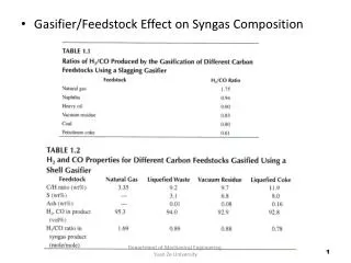
Gasifier/Feedstock Effect on Syngas Composition
180 likes | 497 Views
Gasifier/Feedstock Effect on Syngas Composition. 1. Department of Mechanical Engineering, Yuan Ze University. Commercial Gasification. 2. Department of Mechanical Engineering, Yuan Ze University. Materials of Construction.

Gasifier/Feedstock Effect on Syngas Composition
E N D
Presentation Transcript
Gasifier/Feedstock Effect on Syngas Composition 1 Department of Mechanical Engineering, Yuan Ze University Department of Mechanical Engineering, Yuan Ze University
Commercial Gasification 2 Department of Mechanical Engineering, Yuan Ze University Department of Mechanical Engineering, Yuan Ze University
Materials of Construction • The gasification chamber is lined with a number of different refractory materials. These materials are determined by the type of carbon feedstock (gas/liquid feed or solid materials like coal or petcoke), whether the gasification chamber is designed to liquefy feedstock ash or keep it as discrete particles, the quantity of ash generated, and if the gasifier sidewalls are air or water cooled. • The refractory lining is designed to provide protection of the steel shell for sustained, uninterrupted periods of time so the gasifier can operate effectively and economically. • A steel shell thickness is determined by internal pressure, shell temperature, and the vessel diameter and range up to 3 inches or more. • A gasifier’s operational temperature has a large influence on liner materials, with gasifiers such as the Sasol-Lurgi (figure 1.3e) operating at temperatures below the ash liquification (ash impurities remain as a dry particulate). It uses a refractory liner designed to withstand abrasive wear, the gasification atmosphere, and the high operating temperature. • Gasifiers that form molten slag focus on chemical wear and corrosion. Most gasifiers produce a molten ash (slag) that is highly corrosive, causing high refractory wear that negatively impacts refractory service life. 3 Department of Mechanical Engineering, Yuan Ze University Department of Mechanical Engineering, Yuan Ze University
High alumina brick or monolithic refractory materials are predominantly used as hot face liners in gas or liquid feedstock gasifiers, and high chrome oxide or high thermal conductivity materials with coal or petcoke feedstock. • The service life of different refractory linings varies, with those using oil as a carbon source typically lasting 4 to 5 years (high-wear areas may need replacement in as short as 2 years), gas up to 10 years (various areas of the gasifier requiring replacement between 6 and 10 years), and solid feedstock (coal or petcoke feedstock) up to 2 years (high-wear areas may require replacement in as little as 3 months). • Refractory liners used in a gas or liquid gasifier are typically high alumina materials (94 to 99 % Al2O3) that are low in SiO2 and FeO, while material used in solid-fuel air-cooled slagging gasifiers are high in chrome oxide (up to 95 % Cr2O3) . • Gasifiers that use biomass feedstock have unique requirements due to the high alkali and alkaline earth oxide, components that vigorously attack any refractory linings. Department of Mechanical Engineering, Yuan Ze University
5 Department of Mechanical Engineering, Yuan Ze University Department of Mechanical Engineering, Yuan Ze University
Materials Development for Sulfur-Iodine Thermochemical Hydrogen Production • The sulfur-iodine (S-I) cycle is a thermochemical water-splitting process that utilizes thermal energy from a high-temperature heat source to produce hydrogen (H2). • It is comprised of three coupled chemical reaction as shown in figure 4.1. • First, the central low-temperature Bunsen reaction (Section I) is employed to produce two liquid phases from sulfur dioxide (SO2) , iodine (I2) , and water (H2O). Under proper conditions, these two phases become immiscible and can be readily separated. The lighter upper phase is sulfuric acid (H2SO4) , and the denser lower phase is an aqueous complex of HI, H2O, and I2 (HIX). After separation, the two liquid phases are sent to the two other sections for decomposition. • Section II (H2SO4 decomposition) first concentrates the sulfuric acid that has been received from Section I and then decomposes it into SO2, O2 and H2O at high temperature. The decomposed products are returned to Section I to continue the S-I cycle. • In section III (HI decomposition) HI is distilled from HIX and is then decomposed into H2 and I2 at intermediate temperature. H2 is separated for external use and iodine is cycled back to Section I to support the Bunsen reaction. • The key advantages of the S-I cycle are that it has no effluent and the reactants are in easily transportable liquid or gaseous form. All the chemicals used are recycled, and the only required process inputs are heat and water. Department of Mechanical Engineering, Yuan Ze University
Heat sources that are capable of delivering the high temperature required by H2SO4 decomposition reaction include the modular helium reactor (MHR), high-temperature solar tower, and coal- and natural gas-burning plant. • Figure 4.2 shows a schematic of a conceptual S-I hydrogen-electricity co-generation plant design that is supported by the heat generated by a high-temperature nuclear reactor. • The heat that is required to drive the two decomposition reactions and the electric turbine is delivered through an intermediate heat exchanger that employs helium gas as the heat transport medium. • Other intermediate-loop medium, such as molten fluoride salt, have also been proposed for this application. Department of Mechanical Engineering, Yuan Ze University
The S-I cycle is capable of achieving an energy efficient of 50 %, making it one of the most efficient cycles among all water-splitting processes. • In addition, the S-I cycle is similar to other chemical production processes in that it is highly suitable to scaling up to large-scale production of H2. • Hence, it has good potential to deliver large quantities of low-cost hydrogen. Department of Mechanical Engineering, Yuan Ze University
11 Department of Mechanical Engineering, Yuan Ze University Department of Mechanical Engineering, Yuan Ze University
12 Department of Mechanical Engineering, Yuan Ze University Department of Mechanical Engineering, Yuan Ze University
13 Department of Mechanical Engineering, Yuan Ze University Department of Mechanical Engineering, Yuan Ze University
14 Department of Mechanical Engineering, Yuan Ze University Department of Mechanical Engineering, Yuan Ze University
S-I Cycle Demonstration Department of Mechanical Engineering, Yuan Ze University
Materials Development for The S-I Cycle • There are three ongoing material research areas that are important for the eventual success of the S-I cycle. • First and foremost is the development of construction materials that can handle the corrosive environment for the lifetime of the process equipment, especially heat exchangers, boilers, and reactors. • The second area involves gas-permeable membranes. • The third area involves catalyst development. • Identifying suitable membranes and reaction catalyst can improve the efficiency of the overall cycle and make H2 production more economical. • Effort is currently ongoing in all three disciplines to find the optimal material solutions. Department of Mechanical Engineering, Yuan Ze University
17 Department of Mechanical Engineering, Yuan Ze University Department of Mechanical Engineering, Yuan Ze University
18 Department of Mechanical Engineering, Yuan Ze University Department of Mechanical Engineering, Yuan Ze University