Impulse Response (IR)
Impulse Response (IR). Applications: Pile integrity testing Floor slabs, walls and pavements Concrete consolidation Cylindrical structures (silos, chimney stacks and tanks) Concrete bridges Cladding on high-rise buildings. Impulse Response Method.

Impulse Response (IR)
E N D
Presentation Transcript
Impulse Response (IR) Applications: • Pile integrity testing • Floor slabs, walls and pavements • Concrete consolidation • Cylindrical structures (silos, chimney stacks and tanks) • Concrete bridges • Cladding on high-rise buildings
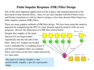
Impulse Response (IR): Fundamentals in Pile Testing • Low strain impact on pile head generates axial bar wave (compression stress) • Impact force measured by load cell • Response to impact measured by velocity transducer (geophone) in time domain • FFT on force and velocity, combined to give transfer function: Mobility (v/F) v. frequency • Theory well established
Impulse Response (IR): Basics in Structure Testing • Low strain impact on structural element generates compression stress wave (as in Impact-Echo method, but lower frequency band [0-800 Hz] & much greater force input) • Impact force measured by load cell • Response to impact measured by velocity transducer (geophone) in time domain • FFT on force and velocity, combined to give transfer function: Mobility (v/F) v. frequency
IR Parameters – Structure Testing • Dynamic stiffness in MN/mm from mobility slope between 0-50 Hz • Average mobility from 100-800 Hz (function of element thickness and concrete quality) • Slope of average mobility (function of concrete consolidation and proximity of structural shape changes) • Peak/average mobility ratio (support beneath slabs on grade, voiding)
Example of IR Slab Test Stiffness Average Mobility
IR from Highway Pavement Voiding beneath slab
IR from Cooling Tower Honeycomb Mobility Slope
Impulse Response Test Output Mobility Plots Test point indicating low thickness and good support (Black) Test point indicating good thickness and good support (Blue)