Download

1 / 39
410 likes | 644 Views
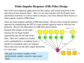
Learn about designing Infinite Impulse Response (IIR) and Finite Impulse Response (FIR) filters for digital signal processing. Explore methods, specifications, and approaches for developing stable transfer functions.

E N D
CHAPTER 5 INFINITE IMPULSE RESPONSE FILTER
CONTENTS 5.1 Brief Introduction to IIR 5.2 Impulse Invariance 5.3 Bilinear Transformation 5.4 Analog-Digital Transformation
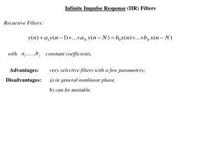
Digital Filter IIR--h(n) infinite length FIR--h(n) finite length Recursively Non-recursively Different methods to design IIR filter and FIR filter !
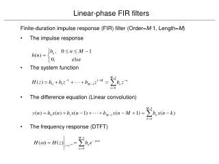
Process of filter design • Three basic steps: • Requirement analysis: • Type/specification • (1) Lowpass / Highpass / Bandpass / Bandstop • (2) Bandedge frequency • (3) Passband ripple / Stopband attenuation • Objective of digital filter is to develop a casual • and stable transfer function H(z) meeting the • frequency response specification. • Implementation of H(z).
BASIC SPECIFICATIONS FOR DIGITAL FILTER Amplitude-frequency phase-frequency Attenuation of frequency components Delay of frequency components Transition — 3dBpassband cutoff frequency Pass band Stop band
5.1 Basic Approach to IIRdigital filter design An order N IIR digital filter’s system function is: Objective of H(z):Determine coefficient ai andbi or zero and pole point ci and di, in order to meet design requirements. Three approaches to IIR digital filter’s transfer function design • Estimation of transfer function • Iterative optimization technique • Analog filter theory
Pole-zero diagram Geometric evaluation 1 Approach to filter design (1)Estimation of transfer function from diagram Pole inside unit circle Peak in frequency response Zero inside unit circle Valley in frequency response
(2) Iterative optimization technique Iterative optimization technique are used to minimize the error between the desired frequency response and computing generated filter. Large computation cost Computer aided
(3)Application of analog filter theory • Advantage: • Analog approximation techniques are highly advanced. • They usually yield closed form solutions. • Extensive tables are available for analog filter design. • Principle: • DF requirement AF requirement AF’s Ha(s) DF’s H (z) • Basic approach: Impulse invariant; • Bilinear transformation.
模拟滤波器的设计方法 (教材 6.2) 模拟滤波器需求Requirement Ha(s) Butterworth filter Elliptic filter Chebyshev I Chebyshev II
四种模拟滤波器的比较 • 幅频特性: • 巴特沃斯 — 整个频带内单调下降; • 切比雪夫I — 通带内等纹波振动,过渡带/阻带单调下降; • 切比雪夫II —阻带内等纹波振动,过渡带/通带单调下降; • 椭圆—除过渡带外,通带和阻带都等纹波振动。 • 过渡带特性: • 巴特沃斯—最差; • 切比雪夫I,II—居中; • 椭圆—最陡; • 设计复杂性: • 巴特沃斯—相同条件下,阶数最高; • 切比雪夫I,II—居中; • 椭圆—相同条件下,阶数最低;
2 Two basic rules from analog to digital filter (1)Imaginary axis j in s-plane be mapped onto unit circle ejw of z-plane. (Ha(s) H(z)) (2)A stable and casual analog transfer function be transformed into a stable and casual digital transfer function. That is: Re[s]<0 in s-plane unit circle |z|<1 in z-plane.
5.2 Impulse invariant (Time domain) Sampling Theorem 1. Transformation Approximate impulse response ha(t) of analog filter using unit impulse response h(n) of digital filter. Let h(n) equal to ha(t)’s sampling value, that is: h(n)=ha(t)|t=nT If transfer function of analog filter is Ha(s), then transfer function of required digital filter is: H(z)=ZT[L-1 [(Ha(s)]|t=nT]
Analog frequency response Digital frequency response 5.2 脉冲响应不变法 Impulse invariant method 1. 变换思想 Impulse Invariant Method Analog filter Digital filter 使数字滤波器的单位脉冲响应序列h(n)模仿模拟滤波器的冲激响应ha(t)。
模拟滤波器s-平面的极点 s 平面 z 平面 数字滤波器z-平面的极点 2 数字化设计过程 Inverse Laplace z-transform ?
Sampling 沿虚轴周期延拓之后,使用 映射到z平面 3. s平面到z平面映射 Mapping from s-plane to z-plane Periodic copies
Mapping between z-plane and s-plane 系统因果稳定 模拟频率和数字频率
3 数字滤波器与模拟滤波器频响关系 若AF的频响是带限的,且: 此时DF的频响才能不失真重现AF频响。
3 数字滤波器与模拟滤波器频响关系 周期延拓 实际模拟滤波器的频响是非带限的 频谱混叠(该方法严重的缺点) 高通模拟滤波器 周期延拓以后,混叠严重,难以转换到数字域! 适用范围:低通,带通。
Characteristic of Impulse invariant (a) Keep analog filter’s transient signal in time domain. (b) Linear relationship between digital frequency and analog frequency. (c) Ha()must be band limited on , otherwise distortion will happen in digital frequency domain. Attention: This method is not suitable in following situation: (1) Ha() is not band limited or ha(t) change unstably, and the design requirement is very high (2) Highpass filter and bandstop filter.
Maps the entire axis in s-plane to narrow band in s1 plane. 5.3 Bilinear transformation Disadvantage of impulse invariance: aliasing. Tangenttransformation
Mapping of the s-plane into the z-plane s plane s1 plane z plane Image of left half plane Bilinear transformation AF DF
Frequency nonlinear change of bilinear transformation Effect of frequency warping . Prewarp critical bandedge frequency.
(3)Features of bilinear transformation (a) No amplitude-frequencydistortion after transformation, no requirement for Ha()’s bandwidth; (b) Simple design; (c)Non-linear relationship between digital frequency and analog frequency; (d) Frequency warping can be revised by prewarping method. Transient response impulse invariance Other situations bilinear transformation
(4)Procedures from AFilter to DFilter • Specification • Transformation:digital analog • Impulse invariance:=T • Bilinear transformation • Analog filter design • Analog filter Digital filter
解: 第一步:临界数字频率: 第二步:临界模拟频率: 第三步:选择巴特沃斯滤波器,根据 和 求Ha(s) 第四步:求H(z) 例:使用双线性变换法设计一个IIR滤波器,要求: (1)通带阻带具有单调下降的特性; (2) (3)
5.4 Prototype transformation Prototype filter —— Analog lowpass filter Lowpass Bandpass Prototypetransformation: Analog lowpass filter Types of digital filter Bandstop Highpass Typical filter’s “ideal” amplitude-frequency characteristics.
(1)High-pass, Band-pass, Band-stop a. Design method 模拟低通原型 模拟高通、带通、带阻 数字高通、带通、带阻 (1) 模拟低通原型 数字高通、带通、带阻 (2) 模拟低通原型 低通数字原型 数字高通、带通、带阻 (3)
2)Direct transform HP transform Mapping
2)Direct transform BP transform Transform Mapping
2)Direct transform BP transform Transform Mapping
3)z-plane transform Belongs to prototype transform. Design other kinds of digital filters using digital lowpass prototype filter. Mapping: System function H1(z) of digital lowpass prototype filter Required system function Hd(Z) of other filter One z-plane another z-plane One stable casual system another stable casual system
Mapping principle: • Stability unchanged, from unit circle of one plane to • unit circle of another plane. • Frequency response specification meets the same requirements, from unit circle of one plane to • unit circle of another plane. In fact, mapping is rotating on unit circle. For example: LP HO that is rotate with Transform equation and design equation(Next page)
Transform g(z-1) Determination of coefficient Lowpass lowpass Lowpass highpass Lowpass bandpass Lowpass bandstop
Digital filter specification Analog frequency transform Analog/digital transform (1) Digital filter’s system function Analog filter specification Analog low- pass prototype Digital/digital frequency transform Digital lowpass prototype (2) Lowpass Highpass, bandpass and bandstop Digital filter transformation
Review • Approach to IIR design • (1) Estimation of transfer function • (2) Iterative optimization technique • (3) Design digital filter with analog filter (mapping) • Must meets two conditions: • Frequency response simulation: j on unit circle • Casual and stability invariable: • left half on s-plane unit circle
Approach to IIR filter design • (1) Impulse invariance • Application of sampling theorem(time-domain) • Transform: Linear frequency mapping • Frequency aliasing • Applicable to lowpass filter and bandpass filter • (2) Bilinear transformation • s plane z plane (frequency domain) • Transform pair: Non-linear frequency mapping • Design Simply. • (3) Prototype transform • Prototype: Lowpass analog filter Other types of filter • Three types: Analog lowpass AF LP,HP,BP,BS DF • Analog lowpass DF LP,HP,BP,BS • Analog lowpass DFLP DF LP,HP,BP,BS