Download
1 / 20
200 likes | 361 Views
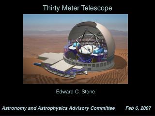
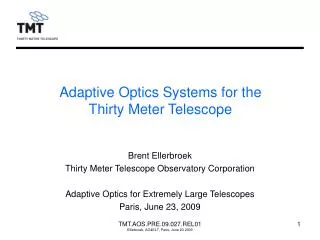
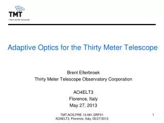
Thirty Meter Telescope Secondary and Tertiary Mirror Systems. International Symposium on Photoelectronic Detection and Imaging 2011 International Colloquium on Thirty Meter Telescope Virginia Ford 25 May 2011. M2 and M3 Systems. Secondary Mirror (M2) System. Tertiary Mirror (M3) System.

E N D
Thirty Meter Telescope Secondary and Tertiary Mirror Systems International Symposium on Photoelectronic Detection and Imaging 2011 International Colloquium on Thirty Meter Telescope Virginia Ford 25 May 2011 TMT.OPT.PRE.11.046.DRF01
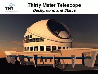
M2 and M3 Systems Secondary Mirror (M2) System Tertiary Mirror (M3) System Primary Mirror (M1) System TMT.OPT.PRE.11.046.DRF01
M2 and M3 Systems M2 Positioner and Control Electronics M3 Cell Assembly M3 Positioner and Control Electronics M2 Cell Assembly M2 System TMT.OPT.PRE.11.046.DRF01 M3 System
M2 and M3 Cell Assemblies: Passive • Passive support systems – non-actuated optical surfaces • M2 and M3 optical surface errors will be corrected by M1 segments • Low-spatial frequency errors are correctible by M1 • Residual fitting errors are within error budget • Image blur from beam footprint motion on M3 is acceptable • Off-axis image shear errors are acceptable EXAMPLE: M2 GRAVITY PRINT-THROUGH PATTERN CORRECTED BY M1 SEGMENTS UNCORRECTED M2 M1 SEGMENT PISTON, TIP, TILT ONLY TMT.OPT.PRE.11.046.DRF01 Surface Peak to Valley = 530 nm Surface Peak to Valley = 54 nm
M2 and M3 Mirror Substrates • Substrate requirements: • Low-speed movements → ultra light weight substrate not required • High thermal stability required • Thermally-induced surface distortions should cause spatially smooth errors • Resistant to chemicals used to clean and strip the coating • Substrate selected: • Very-low expansion glass or glass ceramic • Smoothly varying, low CTE • Resistant to cleaning and stripping chemicals • Meniscus-style substrate form – gravity print-through creates low spatial frequency, smooth, correctable surface errors • Existing technology – no development, low-cost, low-risk TMT.OPT.PRE.11.046.DRF01 TMT.OPT.TEC.11.067.DRF01
M2 and M3 Mirror Polishing Surface Error Requirements • Surface error requirements are controlled as a function of spatial frequency • Low-spatial-frequency allowances are generous to ease polishing and metrology • Well correctible by M1 segments • Mid-spatial-frequency allowances have tighter limits • Partially correctible by M1 segments • Ability to correct decreases as spatial frequency increases • High-spatial-frequency allowances are tightly controlled • Not correctible by M1 segments or the Adaptive Optics (AO) system TMT.OPT.PRE.11.046.DRF01
M2 and M3 Mirror Polishing State-of-the-Art • TMT M2 and M3 mirrors are larger than existing equivalent mirrors that have been produced • Recent advances in polishing techniques and metrology enable their fabrication • M2 State of the art: • MMT convex 1.7 m diameter secondary mirror: • f/1.3; asphericity 330 μm; radius of curvature 5151mm; conic constant 2.7 • TMT convex 3.0 m diameter secondary mirror: • f/1.0; asphericity 885 μm; radius of curvature 6228mm; conic constant 1.3 • M3 State of the art: • 2 m diameter flat (University of Arizona – reported SPIE 2007) • Metrology: subaperture Fizeau interferometry and scanning pentaprism resulting in 3nm rms measurement uncertainty • TMT: 3.5m x 2.5m ellipse TMT.OPT.PRE.11.046.DRF01
Secondary Mirror Polishing Challenges • Since M2 is convex, it cannot be tested from its center-of-curvature • Must fabricate very large test optics or use smaller test optics with subaperture stitching • M2 is highly aspheric • Polishing tool fitting challenges • Especially at the edge of the mirror, the polishing tool size must be small • The tight requirements on high spatial frequency optical surface errors provides challenges to small tool polishing TMT.OPT.PRE.11.046.DRF01
M2 Mirror Polishing Challenges • Asphericity causes tool fit issues: • M2 optical surface is extremely non-spherical (for tool misfit < 1 μm) large spherical tool small spherical tool aspherical surface TMT.OPT.PRE.11.046.DRF01
M3 Polishing Challenges • General issues with large flats: • Edge roll-off • Created by area of polishing tool that is unsupported at edge of part • Elliptical shape issues • Polish mirror as roundel then cut ellipse • Must remove stress relief springing errors caused by cutting or • Cut ellipse then polish • Asymmetrical forces during polishing cause surface errors 2.536 m 3.594 m TMT.OPT.PRE.11.046.DRF01
M2 and M3 Metrology Challenges • Full aperture acceptance testing requires impractical large test optics or subaperture stitching • M2 possibilities for acceptance test: • Fizeau Interferometry • Hindle Sphere or Hindle Shell or Aspheric test plate system • M3 possibilities for acceptance test • Ritchey-Common test • Fizeau Interferometry TMT.OPT.PRE.11.046.DRF01
M2 and M3 Mirror Cell AssembliesAxial Support Systems • Have explored many axial support designs including from 9 to 60-point active and passive • 18-point passive whiffletree supports are sufficient provided some axial print-through can be polished out • 60 point active support: better than required and costly TMT.OPT.PRE.11.046.DRF01
M2 and M3 Mirror Cell AssembliesLateral Support Systems • Passive lateral whiffletree concept study – one concept • 3 meter diameter, 100mm thick mirror Gravity direction Gravity direction LOAD DIRECTIONS (3 PLACES) NELSON & CABAK TMT.OPT.PRE.11.046.DRF01
Support Print-through Polish-out • Polishing-out a portion of support gravity print-through improves performance • Optimize the portion that is polished out – the bias • wavefront variance through the zenith angle operating range • atmospheric degradation effects • With the polish-out portion (bias) optimized for a zenith angle ~30°, surface errors are reduced significantly • Bias Implementation: • During the surface polishing of M2 and M3 with use of small tools • After polishing is completed by sending M2 and M3 to a specialized vendor • Large facility is needed: • Large enough Ion Beam Finishing (IBF) facility • Large enough Magneto Rheologic Fluid (MRF) facility TMT.OPT.PRE.11.046.DRF01
M2 18-point axial support performance – polish-out biased or non-biased JERRY NELSON TMT.OPT.PRE.11.046.DRF01
M2 Positioner • Requirements: • Travel Range of Motion: • Translation: ±15 mm • Rotation: ±413 arcsec • Positioning accuracy: • Translation: 3 μm • Rotation: 0.1 arcsec • Jitter: • Translation: 1 μm RMS • Rotation: 0.05 arcsec RMS • Similar performance to: • Subaru Prime Focus Unit Hexapod • Blanco DECam Hexapod POSITIONER CONTROL SYSTEM FIXED PLATFORM HEXAPOD ARM MOVING PLATFORM TMT.OPT.PRE.11.046.DRF01
M3 Positioner Rotation Axis (θ) Tilt Axis (Φ) Tilt Cradle Rotation Cradle Tilt Actuator Counter-balance weights Rotation Bearing Cable Wrap Not shown: Positioner Control Electronics TMT.OPT.PRE.11.046.DRF01
M3 Positioner • Jitter: • Rotation: 0.1 arcsecrms • Tilt: 0.1 arcsecrms • Requirements: • Positioning accuracy: • Rotation: 0.2 arcsec • Tilt: 0.2 arcsec • Motion of M3 during tracking is a function of instrument location and zenith angle: • Graphs show instrument locations on +X Nasmyth platform only Instrument locations Instrument locations
Summary • TMT M2 and M3 Systems are challenging but can be fabricated • Conceptual designs have been developed that meet requirements • Polishing and metrology are challenging but several facilities in the world are capable of meeting these challenges TMT.OPT.PRE.11.046.DRF01
Acknowledgements The TMT Project gratefully acknowledges the support of the TMT partner institutions. They are the Association of Canadian Universities for Research in Astronomy (ACURA), the California Institute of Technology and the University of California. This work was supported as well by the Gordon and Betty Moore Foundation, the Canada Foundation for Innovation, the Ontario Ministry of Research and Innovation, the National Research Council of Canada, the Natural Sciences and Engineering Research Council of Canada, the British Columbia Knowledge Development Fund, the Association of Universities for Research in Astronomy (AURA) and the U.S. National Science Foundation. TMT.OPT.PRE.11.046.DRF01

![[79.03] The Thirty Meter Telescope (TMT) Project](https://cdn1.slideserve.com/1737456/79-03-the-thirty-meter-telescope-tmt-project-dt.jpg)