Cryogenic Optical Microscope
Cryogenic Optical Microscope. Faculty Advisor: Prof. Greg Kowalski Sponsors: Dale Larson , James Hogle, Ph.D. (Harvard Medical School) Design Team : Mohammad Ali John Delcore Sarah Kaufmann David Rezac. Problem Statement.


Cryogenic Optical Microscope
E N D
Presentation Transcript
Cryogenic Optical Microscope Faculty Advisor: Prof. Greg Kowalski Sponsors: Dale Larson , James Hogle, Ph.D. (Harvard Medical School) Design Team: Mohammad Ali John Delcore Sarah Kaufmann David Rezac
Problem Statement • Infected, frozen sample to be analyzed in TEM • Very high resolution • Required to better understand cell behavior • Imaging complications • Small field of view leads to lots of time searching • Electron bombardment • Congested area around cell (Source: www.brockhouse.mcmaster.ca)
Problem Statement • Infected, frozen sample to be analyzed in TEM • Very high resolution • Required to better understand cell behavior • Imaging complications • Small field of view leads to lots of time searching • Electron bombardment • Congested area around cell` (Source: www.lifesci.ucsb.edu)
Problem Statement (cont.) • It is necessary to first image the sample in an optical microscope (OM) and identify areas of interest • Currently, frozen samples cannot be viewed in the OM (Source: webphysics.davidson.edu)
Design Requirements • Maintain specimen below -140°C • Provide means to image the sample (microscope) • Isolate sample from significant vibrations • Protect sample grid from stresses that may cause deformation • Prevent contamination by water contact (condensation)
Impact Statement • Aid research and development for improved therapeutic advancements • Improve quality and quantity of TEM images • Enable microscopists • Label molecular components in OM • Analyze with high resolution of TEM • Requires no additional expertise • Familiar operations for microscopists
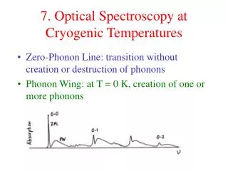
Why below -140oC? • The sample is embedded in vitreous ice • Stable below -140oC • Vitreous ice is the “glassy” amorphous solid form of water • Does not scatter electrons • Low vapor pressure (Source: www.nims.go.jp)
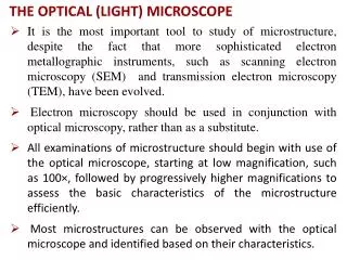
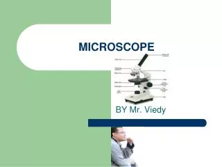
Optical Microscope • Numerical Aperture (NA) • Indicates the resolving power of the lens • Larger NA = better resolution • Inversely related: WD NA (Source: www.microscopyu.com)
Optical Microscope • Numerical Aperture (NA) • Indicates the resolving power of the lens • Larger NA = better resolution • Inversely related: WD NA (Source: www.microscopyu.com)
Design #1 Preliminary Designs Design #2 Design #3
Thermal Modeling TGU=16oC Design #3
Cold Temperature Objective Lens • Able to function at LN2 temperature • Manufactured by Microthek Corp. in Germany • 80x magnification • 0.8 Numerical Aperture • .96 mm working distance • Withstands cyclic testing to liquid helium temperatures
Design Evolution Window (Image Path) Cold Lens Position LN2 Level Vacuum Chamber Inner Skirt to Hold N2 Gas Post to Hold Sample for Imaging Outer Housing
TEM Cryo-Transfer Apparatus • Cold Finger • LN2 Workstation
Current Design Upper Assembly (Contains Objective Lens) Cold Finger Work Station
Current Design LN2 Reservoir
Current Design Sample Position
Boiling CHF (Source: www.alamthermal.com) (Source: www.spaceflight.esa.int) (Source: www.nuc.berkeley.edu)
Boiling • qin=9.47W • SS in 116 minutes • 1.98kg LN2 • qin=3.08W • SS in 26 minutes • 0.075kg LN2
Boiling • qin=9.47W • SS in 116 minutes • 1.98kg LN2 • qin=3.08W • SS in 26 minutes • 0.075kg LN2
Testing Complete Assembly in Imaging Position External Nitrogen Flush Thermocouples in Key Locations
Testing Test #1 Test #2 Pre-Cooled Copper =Tsample Test #3 Test #4
Testing Test #1 Test #2 Pre-Cooled Copper =Tsample Test #3 Test #4
Testing Test 1 Test 2 Test 3 Test 4 Imaging Cutoff
Microscope Aberrations Partial Focus Focused: 2.7µ 10µ Line Spacing (filters omitted) Special Thanks to: Antoine van Oijen Resolution Target
Current Prototype • Allows for imaging in the optical microscope • Stable cold environment maintains specimen below -140°C for 10-15 minutes • Provides imaging resolution down to 2.7µ • Incorporates TEM cold finger into the design • Protects sample from additional stresses or possible water contamination • Saves time and effort • Whole system is on a 1,000 lb optical table • Reduces vibrations
Recommendations • Continue design stage with thermal mass concept • Refine microscope operation • Reduce footprint and isolate optical components • Function specific improvements: • Automate XY and Z stages • Purchase camera suited to application