Download

1 / 29
300 likes | 440 Views
Safety Engineers. CPLD Course Draft International Software Safety Conference 2011. Background.

E N D
Safety Engineers CPLD Course DraftInternational Software Safety Conference 2011
Background • The Naval Ordnance Safety and Security Activity (NOSSA) realized the need to educate and inform the Safety Professionals on CPLDs due to the numerous Contractors that were starting to utilize them in Navy systems. • Proper safety analyses were not being performed. • Booz Allen Hamilton was tasked to develop an introductory course utilizing both Government and Industry sources.
Introduction • In this course, you will learn the basics of Programmable Logic Devices (PLDs). • What are PLDs? • What are the different types? • What are the positives and negatives of using PLDs? • What design and test requirements must be considered? • What the Government boards look for?
PLD Safety Introduction • What is a Programmable Logic Device (PLD)? • Programmable hardware device with no preset functionality / configuration • Functionality / configuration programmed via software (VHSIC hardware description language (VHDL) or schematic capture) • Programmed PLD’s can be used to replace vast amounts of discrete circuitry • PLD’s considered to be highly reliable by Reliability Engineers and vendors when implemented by the manufactures’ specifications and used in a controlled environment for a specified time. • Probability of failure occurrence values of 1x10-20or lower typically assigned using hardware only hard fault per standards (IEEE, ANSI, ASTM, IEC, etc.) • Extremely high reliability values have a great enticement to programs which wish to meet MIL-STD-882 1x10⁻⁶ probability safety requirements (e.g. Autonomous use)
PLD Technologies • Static Random Access Memory (SRAM) • Erasable Programmable Read Only Memory (EEPROM) • Flash • Anti-Fuse
Types of PLD Technologies:Static Random Access Memory (SRAM) • Static Random Access Memory (SRAM): • Infinitely reprogrammable and is normally configured upon power-up by another device such as a configuration Programmable Read Only Memory (PROM) • Programmed information retained only when device is powered (voltage required to retain data varies by vendor – see datasheet) • Some new “Hybrid” Field Programmable Gate Arrays (FPGAs) contain their own internal configuration PROM and are listed in their datasheets as “Non-volatile, Infinitely Reconfigurable”
Types of PLD Technologies:Erasable Programmable Read Only Memory (EPROM) and Flash • Erasable Programmable Read Only Memory (EPROM) & FLASH • Are types of memory that use an array of floating-gate transistors and are programmed using higher voltages than those normally used in digital circuits. • EPROMs can be erased using either UV light or electricity (Electrically Erasable PROM (EEPROM)). • Flash is a type of EEPROM. • Have limited re-programmability (varies by vendor – 100 to 1000 times typical) • Programmed information is retained for years (varies by vendor – 10 to 100 years) • The threshold voltage of the Polysilicon Floating Gate is changed when (Vpp > Vd) Fowler-Nordheim tunneling traps an excess of electrons on the floating gate causingthe transistor to be in the OFF state e- e- e-
Types of PLD Technologies:Anti-fuse • Anti-fuse (fuse technology also exists) • One-time programmable device • An anti-fuse is a high impedance contact (Open State) until it has a relatively high voltage applied to it which turns it into a low-impedance state (Closed State) • Programmed information retained indefinitely (times vary by vendor) • Once fused it cannot be un-fused, thus anti-fuse FPGAs cannot be reprogrammed
Questions to consider when choosing to use PLDs. • How can I be sure that each and every device is programmed as designed? • Once programmed, is it possible for a PLD’s emulated circuit design (functionality / configuration) to inadvertently change? • What is the reliability of PLD devices from a safety viewpoint? • If different from the value provided by Reliability Engineering, why? • Can they be safely used for autonomous control of safety critical applications?
General Physical Failure Modes Potential Mitigations: Use manufacturer data integrity specification and a robust data integrity checking scheme. Use proper grounding techniques Use appropriate vendor/part Use proper encapsulation Adhere to manufacturer specification • Joint Electron Device Engineering Council (JEDEC) identified hardware failure modes which are tested by all vendors (See JEDEC or vendor websites for more information): • Time-dependent dielectric breakdown • A conductive path in the dielectric which shorts the polysilicon’s anode to the cathode resulting in a loss of charge on the polysilicon • Surface inversion • An accumulation of drifted ions which increase the mechanical stress on a device causing loss of charge on the polysilicon floating gate • Electromigration • Accumulation of aluminum ions which may cause fractures to occur within the device leading to internal electrical failures • Corrosion • Devices with pure aluminum subjected to moisture • Temperature cycling / thermal shock • Fatigue failure leading to lifted bonds, fractured / broken bond wires, solder fatigue, cracked die, or a lifted die For further details on potential mitigations, consult your CHENG.
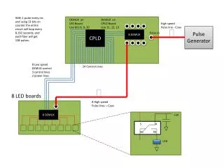
How do you Mitigate Single Event Effects? • Safety Interlock • For this discussion, a safety interlock can be anything downstream that prevents a PLD devices outputs from causing a safety mishap due to a worst-case failure • EXAMPLE: Which devices can be considered as interlocks? These are the only interlocks! Note: Worst-case failure of either SW or MOSFET will result in loss of this single interlock!
Other Safety Interlock Examples Using An Alternate Interlock Technology - Interlocks for FPGA include CPLD, or inline chip, or MOSFET associated with CPLD.
PLD Safety Requirements • There are 23 mandatory PLD Safety Requirements to consider when developing a project where PLDs are used. • 20 Design Requirements • 1 Analysis Requirement • 2 Test Requirements • There are also four recommended requirements that should be done to further reduce risk caused by PLDs. • These requirements are not all encompassing. Project variables could lead to additional requirements.
PLD Requirements • Programmable Logic Devices shall be programmed to power-up and power-down in a known safe state. • Signal input rise times into safety critical PLDs shall meet vendor datasheet requirements. • Failure of meeting input rise time requirements may result in the PLD becoming upset at any time. • PLDs considered being either a High, Serious, or Medium safety risk that utilize sequenced logic to activate safety critical functions shall ensure that out-of-sequence safety critical inputs do not result in a safety critical output. • Safety critical circuitry (SC) with identified SC PLDs should be tested utilizing the same equipment which will be used in the end-design.
PLD Information Safety Summary • Extremely high reliability values given to PLD devices do NOT reflect their susceptibility to Single Event Upset (SEU) failure mechanisms or human error in device configuration / set-up • System Safety must assume a much higher reliability value (probability of occurrence) for these parts (e.g. no lower than 1x10⁻⁴ for proven stable parts or 1x10⁻² for unstable PLDs) • PLD stability and interlocks external to PLDs are critical to show safety boards your system is safe • EEPROM & SRAM based PLD devices are very susceptible to SEUs and therefore are unsuitable for autonomous control over safety critical functions • Anti-fuse based PLD devices are slightly susceptible to SEUs but provide better mitigation against most PLD failure modes • May be used for autonomous control over some lower risk safety critical functions
Quiz • Match each of the definitions with the appropriate type of PLD technologies: • 1. Infinitely reprogrammable and is normally configured upon power-up by another device such as a configuration Programmable Read Only Memory (PROM). • 2. This is a 1 time programmable device and programmed information is retained indefinitely. • 3. This PLD type is a non-volatile memory chip made of floating-gate transistors that retains programmed information for years. It is reprogrammed using UV light.a. Static Random Access Memory (SRAM)b. Erasable Programmable Read Only Memory (EPROM)c. Flashd. Anti-Fuse
Related PLD Guidance Documents • MIL-STD-1901A • 4.8 Electronic Logic Functions. Any electronic logic related to safety functions performed by the Ignition System (IS) or Ignition Safety Device (ISD) shall be embedded as firmware or hardware. Firmware devices shall not be erasable or alterable by credible environments which the IS or ISD would otherwise survive. • FESWG PLD Guidelines • 2.1. To minimize the subversion of Safety Functions (SFs) due to unintentional and/or unrecognized modes of operation, including failure modes, each SF implemented with logic shall use the least complex logic device that can practically perform the required functionality. • 2.2. To avoid degradation of a safety feature or provision for arming delay, any logic device used in the implementation of that feature or provision for arming delay: • 2.2.a. Shall not be re-programmable or corruptible by intentional or unintentional means. Shall not unsafely degrade the SF. Properly implemented fixed-in-structure devices are acceptable to the Services. • 2.2.b. Shall not have the SF logic configuration reside on volatile memory. • 2.2.c. Should be rated by the manufacturer to meet or exceed the lifecycle environments of the system. Otherwise, provide engineering rationale and associated risk(s) for logic devices not rated to meet or exceed the lifecycle of the system. Ask your CHENG for a copy of these and other standards and guidelines.
Note 1: This PLD safety process does NOT apply to the design of Electronic Safety Arm Devices (ESADs) or Arm-Fire Devices (AFDs) Note 2: This PLD safety process was developed with the inputs of various USN / USAF safety board members and NASA’s Office of Logic Design Programmable Logic Device (PLD) Safety Process
PLD Safety Process Introduction • What is the PLD Safety Process? • It is a process designed to integrate with the PLD development process into the overall system safety assessment. • It provides a step-by-step top-level view of how PLD safety can be performed through the various stages of a development program. • It can also be used to determine if a mature system’s use of a PLD is being done in a safe manner. • Why is a PLD Safety Process needed? • Modern circuit designs are starting to use PLD devices, such as FPGAs and CPLDs, to control safety critical functions on an increasing basis • Designers are typically not aware of PLD devices susceptibility to Single Event Upset (SEU), therefore they consider PLD to be very reliable • Those that are aware of SEUs typically assume that basic SEU mitigation techniques provided by vendors are sufficient to prevent a safety mishap • No other process exists on how to analyze or perform PLD safety Congressional policy and Cyber security requirements will soon be released.
PLD Safety Process Introduction • What this PLD Safety Process will or will not do for you • You will notbecome a PLD Expert (e.g. VHDL programming, testing, etc..). • You will notbecome a PLD failure expert. • You will become familiar with the PLD safety requirements that Government safety boards look for. • You will be aware of the process a PLD must go through to safely integrate it into a safety critical system. • You will be able to select appropriate resources to do the safety tasks of the PLD safety process.
Interview with Todd Issac • Why is having a PLD Safety Process important? • When should the safety process be implemented? • Are all the steps in the process important? • Who are the people involved in the safety process? • What are some drawbacks for not having a safety process?
PLD Safety Process Flow • The PLD Safety Process is broken down into Six Steps. The results of each step corresponds to particular sections of the PLD Safety Worksheet. • Step 1: Identify all PLD devices, Tag all safety critical (SC) PLD devices, Apply PLD safety requirements, and identify all in-system interlocks • Step 2: Determine PLD HRI and PLD suitability • Step 3: Perform worst-case PLD safety analysis • Per NASA’s Office of Logic Design, PLD is best analyzed using a “Worst-Case” approach. • Step 4: Complete PLD safety worksheets and perform PLD testing • Step 5: Continuous monitoring of CM and creating of PLD Safety Analysis Report • Step 6: Perform a PLD change analysis after V&V testing is complete
Quiz • For Firmware with High Criticality, an Antifuse and SRAM technology combination will result in a Medium Level of Rigor. • A PLD SME or Safety Engineer is required to do Step 2: Determine PLD HRI and PLD suitability.
PLD Safety Process Conclusion • PLD Safety Process provides a structured method that any Safety Engineer, regardless of technical background, can follow to keep a system safe • This PLD safety process was developed to help Safety Engineers understand the minimum level of effort required for the various combinations of technology to satisfy Government Safety Boards • PLD devices can be used safely within safety critical systems only if proper PLD/HW technology combinations are used and appropriate safety interlocks exist downstream of the PLD devices The end-result of this new PLD safety process is the introduction of a safe product for customer utilization!