Next Generation Digital Back-ends at the GMRT
310 likes | 566 Views
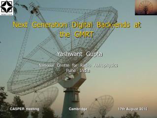
Next Generation Digital Back-ends at the GMRT. Yashwant Gupta National Centre for Radio Astrophysics Pune India. CASPER meeting Cambridge 17th August 2010. 1 km x 1 km. 14 km. The GMRT : some basic facts.

Next Generation Digital Back-ends at the GMRT
E N D
Presentation Transcript
Next Generation Digital Back-ends at the GMRT Yashwant Gupta National Centre for Radio Astrophysics Pune India CASPER meeting Cambridge 17th August 2010
1 km x 1 km 14 km The GMRT : some basic facts • The Giant Metre-wave Radio Telescope (GMRT) is an international facility operating at low radio frequencies (50 to 1450 MHz) • Consists of 30 antennas of 45 metres diameter, spread out over a region of 30 km diameter • Currently operates with a max BW of 32 MHz at 5 different bands : 150, 235, 325, 610 and 1420 MHz • Supports interferometry as well as array mode of operations correlator + beamformer + pulsar receiver • Operational and open to international participation since 2002; has about 40% users from India, 60% from outside ; more than a factor of 2 oversubscribed
The GMRT : some basic facts • The Giant Metre-wave Radio Telescope (GMRT) is an international facility operating at low radio frequencies (50 to 1450 MHz) • Consists of 30 antennas of 45 metres diameter, spread out over a region of 30 km diameter • Currently operates with a max BW of 32 MHz at 5 different bands : 150, 235, 325, 610 and 1420 MHz • Supports interferometry as well as array mode of operations correlator + beamformer + pulsar receiver • Operational and open to international participation since 2002; has about 40% users from India, 60% from outside ; more than a factor of 2 oversubscribed
Upgrading the GMRT • The GMRT has already produced some interesting results and, even in the current configuration, will function as a competitive instrument for some more years. • However, we are working on an upgrade, with focus on : • Seamless frequency coverage from~ 30 MHz to 1500 MHz, instead of the limited bands at present design of completely new feeds and receiver system. • Improved G/Tsys byreduced system temperature better technology receivers • Increased instantaneous bandwidth of 400 MHz (from the present maximum of 32 MHz) modern new digital back-end receiver • Revamped servo system for the antennas • Modern and more versatile control and monitor system • Matching improvements in offline computing facilities and other infrastructure
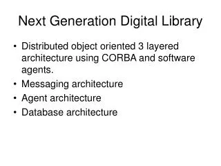
Development of new back-ends for the GMRT For existing 32 MHz system • The GMRT Software Back-end (GSB) -- with CITA • GMRT Transient Analysis Pipeline : GSB + GPUs -- with Swinburne • 300 MHz Wideband Pocket Correlator on the Roach -- with CASPER + SKA-SA • Packetised Correlator for 400 MHz, 4 antennas, dual pol -- with CASPER + SKA-SA • GPU based correlator -- with Swinburne For 400 MHz GMRT upgrade system
The GMRT Software Back-end (GSB) • Software based back-ends : • Few made to order hardware components ; mostly off-the-shelf items • Easier to program ; more flexible • GMRT Software Back-end (GSB) : • 32 antennas • 32 MHz bandwidth, dual pol • Net input data rate : 2 Gsamples/sec • FX correlator + beam former • Uses off-the-shelf ADC cards, CPUs & switches to implement a fully real-time back-end • Raw voltage recording to disks, for all antennas; off-line read back & analysis • Currently status : completed and released as observatory facility Jayanta Roy et al (2010)
The GMRT software backend : block diagram Jayanta Roy et al (2010)
IA Beam ADC 16 MHz or 32 MHz (with AGC) Int Delay Correct Filter + Desamp FFT + FSTC & Fringe Beam former 64 analog Inputs (32 ants, 2 pols) PA Beam MAC visibilities GSB Software flow : real-time mode
GSB : Performance Optimisation • Network transfer optimisation : jumbo packets • Computation optimisation : • Intel IPP routines (for FFT) • Vectorised operations • Cache optimisation • Multi-threading load balancing • Performance specs : • Better than 85% compute efficiency • $190 / baseline ; 250 Mflops / W Jayanta Roy et al (2010)
GSB Sample Results : Imaging • J1609+266 calibrator field at 1280 MHz • 8.5 hrs synthesis image • Central source : 4.83 Jy • Noise level at HPBW : 34 microJy • Dynamic range achieve : ~ 1.5 x10⁵
GSB Sample Results : Beamforming • Phasing the array using a point source calibrator • Single pulses from PSR B0329+54
New Capabilities : RFI mitigation • MAD filtering on raw time resolution data to eliminate bursty, time domain RFI : works very nicely Jayanta Roy et al (2010)
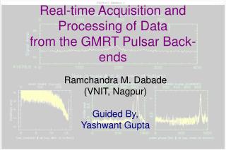
Transient Detection Pipeline at the GMRT (collaboration with Swinburne & Curtin) • To look for fast transients : naonsec to 100’s of millesec; will run in piggy-back mode with any other observation • Exploits multi-element capability of the GMRT & availability of software backend
Transient Detection Pipeline at the GMRT • Event detection : based on the sensitivity of 8 antennae incoherent array beam over 32 MHz, using multiple sub-arrays • Coincidence or anti-coincidence filter : Multiple sub-array multiple beam coincidencefilter reduces the false triggers due to noise or RFI
Transient Detection Pipeline at the GMRT • Search in dispersion measure space : Discriminate fast radio transients from RFI • Real-time trigger generation accompanied by recording of identified raw voltage data buffers off-line detailed imaging analysis to localise the transient source CPU + Tesla GPU
GPUs for Incoherent Dedispersion • Each CPU-GPU combination handles data from one sub-array beam from the GSB : 256 channels across 32 MHz, 15 microsec time resolution • Data is buffered into a shared memory, is read out and passed to the GPU in overlapping blocks • GPU does dedispersion for multiple DMs in real-time and sends the dedispersed time series back to the CPU • Benchmarks : 256 chans, 32 MHz bandwidth, 15 microsec sampling, 1 to 5 sec data • single Tesla can do upto 1000 DMs at real time rate • (collaboration with Swinburne University of Technology)
Specifications : 30 stations 400 MHz BW (instantaneous) 8 - 16 K Freq Channels Full polar mode Coarse and Fine Delay correction Fringe rotation Interferometer with dump times ~ 100 ms Incoherent and Phased array beam outputs : at least 2 beams for each; with full time resolution Pulsar back-ends attached to the beam outputs GMRT Upgrade : Digital Backend Requirements • Approach : • FPGA based system using Roach boards ( starting with the PoCo ) • Hybrid back-end using FPGA + CPU-GPU units
Sample Results : wideband PoCo • 2 antenna, 300 MHz BW wideband Pocket Correlator on Roach board • Full delay correction (integer and fractional sample) • Fringe correction • Tested with wideband signals from GMRT antennas
Sample Results : wideband PoCo • 2 antenna, 300 MHz BW wideband Pocket Correlator on Roach board • Full delay correction (integer and fractional sample) • Fringe correction • Tested with wideband signals from GMRT antennas
Packetised Correlator Design (collaboration with SKA-SA + CASPER) ADC (2 channels) Roach (F engine) Roach (X engine) Switch (10 Gbe) Antenna 1 (400 MHz 2 pols) ADC (2 channels) Roach (F engine) Roach (X engine) Antenna 2 (400 MHz 2 pols) ADC (2 channels) Roach 2 (F engine) Roach (X engine) Data Acquisition and Control Roach (X engine) Antenna 32 (400 MHz 2 pols) Roach (X engine) Roach (X engine)
First Results from Packetised Correlator at the GMRT 11th August 2010 ! • 4 antenna, dual pol, 400 MHz packetised correlator • 2 F engine Roach boards • 4 X engine Roach boards • Delay correction tested • Fringe correction tested Collaboration with SKA-SA team
Software Correlator Design (collaboration with Swinburne) Switch (10 Gbe) Data Acquisition and Control CPU + GPU (F+X engine) CPU + GPU (F+X engine) CPU + GPU (F+X engine) Antenna 1 (400 MHz 2 pols) ADC (2 channels) CPU + GPU machine (F + X engine) Antenna 1 (400 MHz 2 pols) ADC (2 channels) CPU + GPU machine (F + X engine) Antenna 1 (400 MHz 2 pols) ADC (2 channels) CPU + GPU machine (F + X engine)
First Results from GPU Correlator at the GMRT • 2 antenna, 200 MHz design • iADC + iBoB sending data at 800 Mbytes/sec to a Nehelam CPU • Data written to shared memory ring buffer after on-the-fly delay correction • Data read from shared memory and sent to GPU for FFT + MAC operations Collaboration with Swinburne team
Benchmarks for various options • Target : 32 station, 400 MHz, full polar correlator • Single Tesla GPU (fairly optimised code – achieves ~ 220 GFlops on the Tesla) : • ~ 8 MHz bandwidth for FFT + MAC ~ 50 GPUs • ~ 13 MHz bandwidth for MAC only ~ 30 GPUs • 8 core Nehelam machine (with optimised GSB code) : • ~ 2 MHz bandwidth for FFT + MAC 200 machines ! • ~ 8 MHz bandwidth for MAC only 50 machines • Note : single 10 Gbe connection per CPU/GPU machine restricts usable bandwidth to ~ 6.5/13 MHz for 8/4 bit data • Comparison : All Roach solution requires 32 boards for F engines and 64 boards for X engines 96 Roach boards • Possible hybrid solution : use Roach for F engines and GPUs for the X engines
Antenna 32 (400 MHz 2 pols) CPU + GPU (X engine) ADC (2 channels) Roach (F engine) CPU + GPU (X engine) Switch (10 Gbe) Antenna 1 (400 MHz 2 pols) ADC (2 channels) Roach (F engine) CPU + GPU (X engine) Antenna 2 (400 MHz 2 pols) ADC (2 channels) Roach 2 (F engine) CPU + GPU (X engine) Data Acquisition and Control CPU + GPU (X engine) CPU + GPU (X engine) Hybrid Correlator Design
Benchmarks for various options • Target : 32 station, 400 MHz, full polar correlator • Single Tesla GPU : • ~ 8 MHz bandwidth for FFT + MAC ~ 50 GPUs • ~ 13 MHz bandwidth for MAC only ~ 30 GPUs • 8 core Nehelam machine (with optimised GSB code) : • ~ 2 MHz bandwidth for FFT + MAC 200 machines ! • ~ 8 MHz bandwidth for MAC only 50 machines • Note : single 10 Gbe connection per CPU/GPU machine restricts usable bandwidth to ~ 6.5/13 MHz for 8/4 bit data • Comparison : All Roach solution requires 32 boards for F engines and 64 boards for X engines 96 Roach boards • Possible hybrid solution : use Roach for F engines and GPUs for the X engines • Hybrid solution also useful for recording of raw voltages for special modes of observations, test and debug purposes etc.
Talk Layout • GMRT intro – 2 slides : OK • GMRT current specs : RF, BW, back-end – needs one more slide? • GMRT upgrade overview : needs some mods? • Outline of GMRT back-end development (along with collaborations) • Development of back-ends : part I : GSB • Transient analysis pipeline with GSB GPU based processing • Specs for upgrade back-end ; FPGA & hybrid possibilities • Sample results from wideband PoCo : with delay and fringe tracking ; longest sequence of fringe stopped data? pics ? • 32 ant, 400 MHz, full polar, BE layout : general architecture • All FPGA architecture ; SA collaboration • Hybrid architecture ; Swinburne collaboration • Some results :: • Wideband PoCo on Roach : with delay and fringe correction • 4 ant packetised design with delay and fringe correction • 2 ant, 200 MHz, iBoB + GPU design ; CPU benchmarsk also ? • Some numbers : • 32 station, all Roach design • 32 stations, CPU-GPU design • Designs with raw voltage recording • Future Prospects
Software flow : real-time mode 64 analog Inputs (32 ants, 2 pols)