Digital Comparator
Digital Comparator. Digital Comparator.

Digital Comparator
E N D
Presentation Transcript
Digital Comparator • Binary comparators also called digital comparators or logic comparators, they are combinational logic circuits that are used for testing whether the value represented by one binary word is greater than, less than, or equal to the value represented by another binary word. There are Two basic types of comparators. • Equality comparators. • Magnitude comparators.
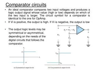
Equality Comparators • An equality comparator, such as that illustrated in Fig below is the simplest multi-bit logic comparator, and can be used for such circuits as electronic locks and security devices where a binary password consisting of multiple bits is input to the comparator to be compared with another preset word. Fig. 1 Four Bit Equality Comparator
A logic 1 will be present at the output if the two input words match, otherwise the output remains at 0. Therefore there is only one input combination that is correct, and the more bits the input words possesses, the more possible wrong combinations there are. With extra circuitry for counting, additional security may be provided by limiting the number of tries before the input is inhibited. • The circuit of the equality comparator consists of an exclusive NOR gate (XNOR) per pair of input bits. If the two inputs are identical (both 1s or both 0s) an output of logic 1 is obtained. • The outputs of the XNOR gates are then combined in an (AND gate), the output of which will be 1, only when all the XNOR gates indicate matched inputs.
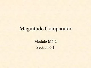
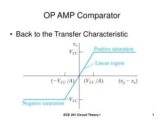
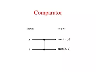
Magnitude Comparators The magnitude comparator can also be used to indicate equality, but has a further two outputs, one that is logic 1 when word A is greater than word B, and another that is logic 1 when word A is less than word B. Magnitude comparators therefore form the basis of decision making in logic circuits. Any logical problem can be reduced to one or more (sometimes many) yes/no decisions based on a pair of compared values. Fig. 2 One Bit Magnitude Comparator
A simple 1-bit magnitude comparator is shown in Fig 2. Gate 3 produces the function A>B and gate 1 gives A<B while gate 2 is an XNOR gate giving an equality output. This basic circuit for a magnitude comparator may be extended for any number of bits but the more bits the circuit has to compare, the more complex the circuit becomes. Integrated circuit magnitude comparators are available that can be used to provide comparisons between multi-bit words. One such IC is the (74HC85 CMOS 4-bit magnitude comparator) shown in Fig below. This IC compares two 4-bit words and provides an output on pins 5, 6 and 7 that indicate whether the input words are equal, or if not, whether A or B has the higher numerical value. Fig. 3 74HC85 Four Bit Magnitude Comparator
Medium Scale Integrated (MSI) Devices • Fig. 4 shows a simplified circuit of a typical four−bit comparator, based on the 74HC85 IC with input and output buffers omitted. If you have been studying previous digital electronics modules with learn about electronics, you may notice that the level of complexity in Fig 4 is much greater than in previous circuits. It was stated that any digital circuit relies on just a few types of logic gate (AND, OR, NAND, NOR, NOT, XOR and XNOR) and even this list can be reduced by utilizing just AND NOR and NAND to obtain the other logic functions. Therefore more complex logic circuits still use combinations of these basic functions but it is the connections between them, and the rapid increase in the number of gates used that adds to the complexity. Fig 4 Medium scale integrated (MSI) devices
ICs like the 74HC85 are called 'Medium Scale Integrated' or MSI devices to distinguish them from SSI (Small Scale Integrated) devices such as the basic logic gate ICs. • Although these devices seem complex is interesting to compare the number of individual transistors in this circuit with those used in the circuits described in earlier modules. Fig 4 shows 31 gates (not including the omitted input and output buffer gates), and each gate comprises about 4 transistors per gate giving a total transistor count for this typical MSI chip of well over 124 transistors, so it is not surprising that the circuit looks complex! • This one small IC then, contains more transistors than would be found for example in many analogue color TV receivers, however this circuit does much less that would be required of the same number of transistors in a TV, and its operation is much easier to understand, especially if you already understand the operation of basic logic gates. • Note the outputs in Fig.3, for A<B, A=B and A>B on pins 5, 6 and 7, and similar inputs on pins 2, 3 and 4, which enable a number of 74HC85 chips to be connected together to provide magnitude comparators for any word length.
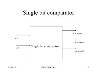
Single Bit Magnitude Comparator • A comparator used to compare two bits, i.e., two numbers each of single bit is called a single bit comparator. It consists of two inputs for allowing two single bit numbers and three outputs to generate less than, equal and greater than comparison outputs. • The figure below shows the block diagram of a single bit magnitude comparator. This comparator compares the two bits and produces one of the 3 outputs as L (A<B), E (A=B) and G (A>B). • The truth table for the single bit comparator is given below. When A0 B0 = 00 & 11, both inputs are equal, therefore A=B output will be high. When A0 B0 = 01, B is more than A and hence AB is active. • From the truth table logical expressions for each output can be expressed as:
2-Bit Comparator • A 2-bit comparator compares two binary numbers, each of two bits and produces their relation such as one number is equal or greater than or less than the other. The figure below shows the block diagram of a two-bit comparator which has four inputs and three outputs. • The first number A is designated as A = A1A0 and the second number is designated as B = B1B0. This comparator produces three outputs as G (G = 1 if A>B), E (E = 1, if A = B) and L (L = 1 if A<B). The truth table of this comparator is shown below which depicting various input and output states.
The figure below shows the logic diagram of a 2-bit comparator using basic logic gates. It is also possible to construct this comparator by cascading of two 1-bit comparators. Fig.5 Two number Comparators each with 2 bits (variables).
4-Bit Comparator • It can be used to compare two four-bit words. The two 4-bit numbers are A = A3 A2 A1 A0 and B3 B2 B1 B0 where A3 and B3 are the most significant bits. • It compares each of these bits in one number with bits in that of other number and produces one of the following outputs as A = B, A < B and A>B. • The output logic statements of this converter are • If A3 = 1 and B3 = 0, then A is greater than B (A>B). Or • If A3 and B3 are equal, and if A2 = 1 and B2 = 0, then A > B. Or • If A3 and B3 are equal & A2 and B2 are equal, and if A1 = 1, and B1 = 0, then A>B. Or • If A3 and B3 are equal, A2 and B2 are equal and A1 and B1 are equal, and if A0 = 1 and B0 = 0, then A > B.
8-Bit Comparator • An 8-bit comparator compares the two 8-bit numbers by cascading of two 4-bit comparators. The circuit connection of this comparator is shown below in which the lower order comparator A<B, A=B and A>B outputs are connected to the respective cascade inputs of the higher order comparator. • For the lower order comparator, the A=B cascade input must be connected High, while the other two cascading inputs A ,B must be connected to LOW. The outputs of the higher order comparator become the outputs of this eight-bit comparator.
The equal output is produced when all the individual bits of one number are exactly coincides with corresponding bits of another number. Then the logical expression for A=B output can be written as • E = (A3 Ex-NOR B3) (A2 Ex-NOR B2) (A1 Ex-NOR B1) (A0 Ex-NOR B0) • From the above output Boolean expressions, the logic circuit for this comparator can be implemented by using logic gates .
Comparators in Cascade • When two or more ICs are cascaded together, as shown in Fig. 7, the outputs of the first IC (representing the least significant 4 bits) are connected to the cascade inputs of the second IC and so on. The final result of the comparison appears on the three cascade outputs of the most significant 4-bit comparator. • To ensure a correct comparison, the cascade inputs of the first (least significant) comparator should be connected as follows: • A<B (pin 2) and A>B (pin 4) = logic 0. • A=B (pin 3) = logic 1. • This also applies to a single IC if only two 4-bit words are being compared.
Comparators in Cascade • The purpose of Digital Comparator is to compare a set of variables or unknown number, for example A (A0, A1, A2, A3,…An, etc) against that of a constant or unknown value such as B (B0, B1, B2, B3,…,Bn, etc) and produce an output condition or flag depending upon the result of the comparison. • For example, a magnitude comparator of two 1 bit (A and B) inputs would produce the following three output conditions when compared to each other (A > B, A = B, A < B).
Fig.11 Eight−Bit Magnitude Comparator two of 4-Bit Comparator
When comparing large binary or BCD numbers like example in the previous slide, to save time the comparator starts by comparing the highest-order bit (MSB) first. If equality exists, A = B then it compares the next lowest bit and so on until it reaches the lowest-order bit (LSB). If equality still exists then the two numbers are defined as being equal. • If an equality is found, either A > B or A < B the relationship between the two numbers is determined and the comparison between any additional lower order bits stops.
Comparators are used in central processing unit s (CPUs) and microcontrollers (MCUs). Examples of digital comparator include the CMOS 4063 and 4585 and the TTL 7485 and 74682. the fig below shows a Comparators using Multiplexers. Fig.12 one Comparators Using Multiplexers the selection lines are connected to each other
Applications of Comparators • Digital comparator are used widely in Analogue-to-Digital converters (ADC) and Arithmetic Logic Unit (ALU) to perform a variety of arithmetic operations. • Used for address checking in computers and microprocessor based devices to select a specific input/output device for the storage of data. • Used in control applications in which the binary numbers representing physical variables such as temperature, position, etc. are compared with a reference value. Then the outputs from the comparator are used to drive the actuators so as to make the physical variables closest to the set or reference value. • Used in Servo-motor control.