Download
1 / 21
210 likes | 232 Views
Minutes of the LEReC Cooling & Merging Sections Meeting held on 28th May 2015. Topics discussed include beam line layout, dipole magnet relocation, bellows bidding, instrumentation, vacuum chamber, and RF cavities.

E N D
Minutes of LEReC Cooling & Merging Sections Meeting28 May 2015 Beam Line Layout – Cooling Section (to be installed by 1 Dec ember 2015) J. Kewisch wants to move the 20 dipole, yellow (to the right) toward the triplet 31.2 cm, maximizing the cooling section length. There will be no interference (e.g., with NSLS corrector magnets). K. Hamdi to work on it. Bid for standard CS bellows (qty-26) came in with good pricing, but Supplier may be taking exception to technical requirements. M. Mapes to resolve. Quotes received for 180 dipole sliding bellows. Beam Line Layout – Merging Cooling Section Jorge to give design guys the magnet and instrumentation layout for incoming transport beam line: BPM, PM, wire scanner, and solenoids. Instrumentation BPM’s: BPM order placed. The smaller BPM’s mounted on the 180 dipole chamber flanges will be converted to ‘hybrid’ BPM’s, a combination of a BPM and a PM. The vertical buttons will be removed and replaced with PM. The existing PM shown near the 180, yellow will be deleted. PM’s and Slits: Dan Weiss close to ordering the motion stage. Magnets HF Solenoids: (Buckley) Delivery estimated to be 8/29/15 + 6 weeks shipping + customs. 180 Dipole Vacuum Chamber: The BPM’s at the chamber inlet and outlet flanges must be positioned with high accuracy, so the 180 chamber flanges must be accurate after welding. There is a possibility that post-weld machining of conflat face will be needed, a costly and risky operation. For the 180 chamber materials M. Mapes has tested a weld with 316 materials for resulting permeability. It was found to be 1.2. Last meeting P. Thieberger said that 1.01 or less is desirable, and not greater than 1.10. The chamber is now being annealed in an oven to try to reduce the slight magnetism. Per M. Mapes the chamber flanges could be rotatable. 180 Dipole Magnet: Drawings are ready. SOW is needed (similar to the existing 20 dipole SOW). Close to submitting WebReq. Beam line components near DC eGun: Meeting with Cornell U. on DC eGun and beam line components conducted earlier in the day. RF Cavities Design of warm RF cavities is currently in process (C. Pai on 704MHz and C. Brutus on 2.1 GHz).
Overall Layout 64 m IP2 H & V Correctors LEReC-I (1.6-2MeV): Gun to dump SRF gun used as a booster cavity Add Quad and Skew Quad Correctors Move BPM close to 180 magnet combine with PM. Add Quad and Skew Quad Correctors
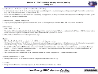
180o Dipole Magnet Neighborhood II Small Aperture BPM’s Both with PM’s ?? HIGH FIELD SOLENOID WINDOW FRAME H&V CORRECTORS LOW FIELD SOLENOIDS w/H&V Corrector ± 4.13” Standard BPM’s Remove H&V PROFILE MONITOR? EMITTANCE SLIT PROFILE MONITOR WINDOW FRAME Quad and Skew Quad CORRECTOR New Horizontal PROFILE MONITOR K Hamdi
180o Dipole Magnet Neighborhood II Aperture Transitions
BPMs in Cooling Section (14 Locations) Orthogonal Installation – simple processing. Large Dia. BPM Housings (4.8 ID), 28mm buttons Drawings complete SOW and Spec complete Requisition approved Order Placed with MPF Special ID for 180 Magnet Same button size Need analysis? Combined with Profile Monitor Eliminate vertical button for PM
20o Dipole Neighborhood Move the 20o dipoles closer to the triplet.
LEReC Dipole Skew Quad Corrector • Window-frame Skew Quad: 100 A-turn per corner = s-quad gradient 3.19 G/cm or, 3.19E-2 T/m • Current polarities: • Opposite corners have the same polarity • Adjacent corners have the opposite polarities.
5 cell cavity location New updates? 5 cell
Overall Layout 3.75”OD/3.62”ID beam line 9.2 cm ID 2.5”OD/2.38”ID beam line (6 cm ID) 5.0”OD/4.78”ID beam line 12 cm ID
Compensating and Matching Solenoids Contract Awarded: 9/15/2015 delivery estimate for both? Buckley magnets complete 8/29/2015 + 6 weeks shipping + customs. Alpha Magnetics update? Design support stand assembly – provide space for mu metal shields, separate beam pipe stand support. Magnetic shielding analysis (Wuzheng) Design prototype mu metal shields and supports. Magnet measurement fixture plan for prototype and design test fixtures.
Cooling Section Profile Monitors Ferrite ring mounting. CMD5005 material. Requisition for commercial vacuum linear stage? YAG screen/mirror holder design complete? Fabrication drawings for YAG screen/mirror holder and vacuum chamber Stage Assembly (Linear Feedthrough) Zero Length adapter flange Profile Monitor YAG Screen Assy.
Cooling Section Emittance Slits Motor drives and position indication specs. approved by vendor. Requisition for commercial vacuum linear stage? Tungsten plate vendor, design adapter tungsten plate to drive shaft flange.
180o Dipole Magnet Requisition Status Range of motion for magnet core +/- 10cm. Magnet Vertical Gap = 10.0 cm (3.94 in.) Vacuum Chamber Aperture = 9.5 cm (3.75 in.)
Vacuum Hardware Beam line bellows & 180 accordion bellows requisition status. “Standard Chamber Length” 180 chamber 316L vacuum annealed to 900C after welding. Test chamber welded and measured. Annealing Shielded valves on order, need DC Gun shielded valves.
20o Dipole Magnet Requisition approved SOW – 2 magnets by 10/1/2015. Order Placed 5/6/2015 Everson Tesla Estimated Delivery 1st two magnets 10/1/2015 Distance Between Pole Faces = 10.4 cm (4.1 in.) Magnet Vertical Gap = 10 cm Vacuum Chamber V Aperture = 9.5 cm (3.74 in.)
20o Dipole Magnet Vacuum Chamber Here attached the wake field analyses of the 180 degree and 20 degree chambers for LEReC. The 180 degree chamber shows a wake loss factor at 0.0186 V/pc, and for the 20 degree chamber, it is 0.0295. Best,Binping Fabrication Drawing
LEReC Cooling Section Design Room Design 180o dipole chamber for impedance review (KH) LF & HF solenoid and 20o dipole fabrication drawings(KH) BPM chamber and buttons (VDM) Beam Line 5” bellows with shields fabrication drawings (GW) 20o dipole vacuum chamber for impedence review (KH) 180o dipole fabrication drawings (KH) Beam Instrumentation ES W slit & chamber fabrication drawings (VDM) Beam Instrumentation PM YAG, mirror, mount, & chamber fabrication drawings (GW) 180o vacuum chamber + large sliding bellows fabrication drawing (KH) Beam Instrumentation PM ferrite insert (GW) 20o dipole vacuum chamber (KH) 20o and 180o stand drawings (KH) Beam line solenoid stand LF Solenoid, BPM, and long pipe are to be independently positioned and surveyed on common stand. Magnetic Shielding drawing and solenoid magnetic measurement test station Cable tray and penetration drawings
LEReC Design Room Phase 2: 5 cell cavity positioning (RM) RHIC 1:00 move real estate drawings (V.DM.) DC Gun Vacuum Chamber Fabrication Drawings (JH) DC Gun SF6 Pressure chamber specification control drawings (JH) DC Gun to Booster SRF booster cavity beam line (JH) DC Gun stands (JH) Phase 2: 5 cell cavity positioning (RM) – Revised Position Phase 1 and 2 cryogenic system layout (RM) 2.1 GHz warm cavity fabrication drawings (MG) 704 MHz warm cavity fabrication drawings DC Gun cathode insertion drive DC Gun cathode coating system upgrade – coating system vacuum chamber Transport line layout drawing (RM/VDM)
Sector 2 Modifications Move cable tray Modify cable tray Move Access Controls Gate Remove stairway and part of cross-over platform
Sector 1 Relocation Remove/relocate cables: instrumentation, cryogenics, vacuum, power Move cable trays