Download
1 / 13
160 likes | 525 Views
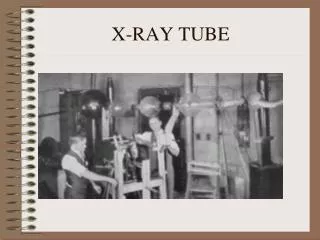
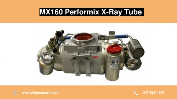
354 Chapt . 6 X-ray Tube. TWO Primary components – cathode and anode Tube must be supported: Ceiling/floor mounted/C-arm, etc. SID’s Detents (center and SID’s) Over ride timer for AEC. Protective tube housing.

E N D
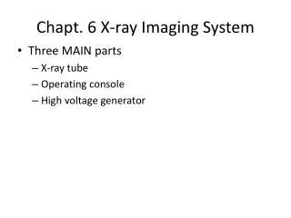
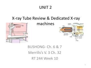
354 Chapt. 6 X-ray Tube • TWO Primary components – cathode and anode • Tube must be supported: Ceiling/floor mounted/C-arm, etc. • SID’s • Detents (center and SID’s) • Over ride timer for AEC
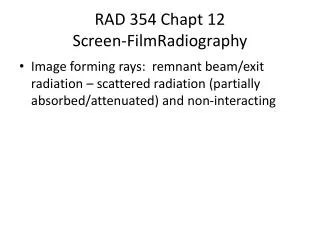
Protective tube housing • X-rays are produced “isotropically” (in all directions) – tube housing allows only those directed at the “window” to escape • Leakage radiation = less than 100 mR/hr at 1 m in any direction other than the window
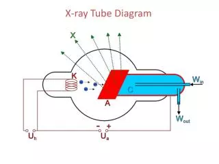
Filament (thoriated tungsten) • 3410 F degree melting point • Tungsten wire – usually 1-2 cm long and 2mm in diameter • Dual filament (equals dual target size) • Thermionic emission • Electron cloud (space charge affect) • NEGATIVELY charged focusing cup • NEGATIVE charged side of x-ray tube
Anode • Most are rotating discs to give MORE surface area for heat dissipation • 3400-10,000 rpm rotation • Angled to give LARGER actual BUT SMALLER effective F.S. • Composite – Tungsten/rhenium • Support arm assembly assists to rid anode of heat and is made of molybdnium/rhenium, tungsten and copper
Other anode attributes • Line-focus principle – actual/effective focal spot • Heel effect • Angles (smaller anode angle = LARGER heel effect • More penetrating beam on CATHODE side due to heel effect
“HEAT” enemy #1! • Tube warm up is required if ONE hour or more has lapsed since the last exposure – CHECK PRIOR TO PLACING PATIENT IN THE ROOM/ON THE TABLE! • PRIMARY reason for tube failure!
Tube rating charts • Variable kVp/fixed mAs – not too practical as kVp is driven by atomic mass density or the patient or contrast agent • Variable mAs/fixed OPTIMUM kVp = most practical as atomic mass number is the “driving force” of kVp and mAs = the amount of radiation produced to make the OD