Download
1 / 32
350 likes | 769 Views
Modeling and Kinematic Analysis of a 6 D.O.F. MOOG Motion Base using Virtual Prototyping tools. Ajay D’Souza Advisor : Dr. Venkat Krovi Mechanical and Aerospace Engineering Department State University of New York at Buffalo. Agenda. Motivation - Need for Virtual Prototyping

E N D
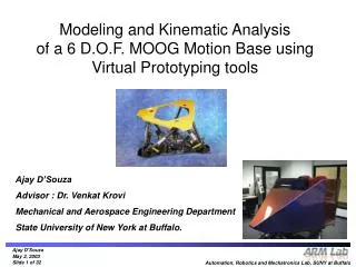
Modeling and Kinematic Analysis of a 6 D.O.F. MOOG Motion Base using Virtual Prototyping tools Ajay D’Souza Advisor : Dr. Venkat Krovi Mechanical and Aerospace Engineering Department State University of New York at Buffalo.
Agenda • Motivation • - Need for Virtual Prototyping • - Project Goals • Background • - Introduction to Robots • - Kinematics of Serial and Parallel Chain Manipulators • Implementation • - Modeling and Simulation of the System • - Tools Employed • Validation/Results • - Validation of the Virtual Model • - Virtual Test Setup • - Results of Simulations • Future Work / Conclusions • - GUI development • - Implications
$$$ 1. Conceptual Design 2. Build Physical Prototype 3. Measure Performance and Test No 4. Modify Physical Prototype Criteria met? Yes 5. Manufacture Product Conventional Approach to Design Motivation Background Implementation Validation/Results FutureWork
1. Conceptual Design 2. Build Virtual Prototype 3. Measure Performance and Test by Simulation No 4. Refine Virtual Prototype Criteria met? Criteria met? Yes 5. Build Physical Prototype 6. Test Physically No Yes 7. Manufacture Product The Virtual Prototyping Alternative Less $$ !!! Motivation Background Implementation Validation/Results FutureWork
Ride Programming • Current Scenario • Joystick based teach pendant method saved as pre-programmed binary ride file • API through which d.o.fs can be set for each time step. • -Prescribing coupled Cartesian motions tends to be difficult Motivation Background Implementation Validation/Results FutureWork
Project Goals • Proposed Approach • Creation of a detailed CAD model (Geometric and Kinematic) • Perform kinematic analyses (Inverse / Forward) • Run validation tests on virtual models • Use validated data for creating ride files Motivation Background Implementation Validation/Results FutureWork
Introduction to Robots • Robotics Institute of America definition of ROBOT: • ‘A re-programmable multi-functional manipulator designed to move material, parts, tools or specialized devices, through variable programmed motions for the performance of a variety of tasks.’ • Structural Classification : • Serial manipulators • Structure takes form of open articulated chain • i.e. one end of the manipulator is attached to the ground and the other end is free to move in space • Parallel manipulators • Composed of one or more closed kinematic loops • i.e. Final link is grounded such that each link in the chain is connected to at least 2 other links Motivation Background Implementation Validation/Results FutureWork
Serial and Parallel manipulators - At a glance Serial Parallel Small Large High Yes Complex, Multiple solutions Complex, Multiple solutions Flight / ride simulator, machining, entertainment, mining equipment, radar positioning Large Small Low No Simple, Unique solution Complex, Multiple solutions Welding, assembly, painting, material handling, pick and place Workspace Load Capacity Precision Passive joints FDA RDA Typical Applications (Courtesy: Ebert-Uphoff, I., Class notes2001) Motivation Background Implementation Validation/Results FutureWork
Boeing 737 flight simulator (l to r: External and interior views) (Courtesy: Ansett flight simulator centre, Melbourne Australia) Quadruped Walking Robot "Tekken-II(Courtesy: University of Electro-Communications Kimura Lab , Japan) Orthoglide parallel kinematic m/c tool (Courtesy: Institut de Recherche en Communications et Cybernétique de Nantes) Applications of Parallel manipulators Bicycle simulator (Courtesy: Vibration Control Laboratory, Korea Advanced Institute of Science and Technology (KAIST)) Motivation Background Implementation Validation/Results FutureWork
F = l (n - j - 1) + Sfi where, F: degrees of freedom of the mechanism fi: degrees of relative motion permitted by joint i n: number of links in a mechanism, including the fixed link j: number of joints in a mechanism, assuming all the joints are binary l: degrees of freedom of the space in which a mechanism is intended to function (l=6 for spatial and l=3 for planar and spherical mechanisms) For the Moog Base we get, F = 6 (14 – 18 – 1) + [(2x6) + (1x6) + (3x6)] = -30 + 36 = 6 Prismatic joint Spherical joint Universal joint Degrees of Freedom = 6 The MOOG motion base Motion Base (Courtesy: MOOG Inc.) More about Parallel Manipulators: www.parallemic.org U-P-S Limb of the Base Motivation Background Implementation Validation/Results FutureWork
End-effector Cartesian coordinates, Forward Kinematics Joint variables, End-effector Cartesian coordinates, Inverse Kinematics Joint variables, Kinematic Analyses Motivation Background Implementation Validation/Results FutureWork
RRR Serial chain robot • 3 Degrees of Freedom • Planar robot End effector a3 P a2 Y a1 X Given to find Serial Manipulators Forward Kinematic Analysis where, Result : Simple, Unique solution Motivation Background Implementation Validation/Results FutureWork
RRR Serial chain robot • 3 degrees of freedom • Planar robot Given to find End effector Squaring each equation and adding them together eliminates . Solving for yields, a3 P a2 Y a1 a3 (+) X (-) 3 a2 (+) a1 (-) 2 (+) 1 Serial Manipulators Inverse Kinematic Analysis 2 solutions for exist in this case leading to 2 configurations yielding the same end-effector location Indeterminacies exist Result : Complicated, Multiple solutions !! Motivation Background Implementation Validation/Results FutureWork
For the inverse kinematics, xA, yA and are given, and the joint anglesare to be found. C h h h B A b1 y a1 D O x P(xp,yp) Parallel Manipulators Planar 3-d.o.f, 3-RRR parallel robot Inverse Kinematic Analysis Parallel robot to be modeled as 3 serial robots and solved Total of (23 ) eight possible manipulator postures corresponding to a given end effector location ! Indeterminacies exist (Courtesy: Tsai, 1999) Result : Complicated, Multiple solutions !! Assumption: AB=BC=AC=h and PQ=QR=RP=c Motivation Background Implementation Validation/Results FutureWork
For the direct kinematics are given and the position xA,yA and orientation angleof the moving platform are to be found. C h h h B A b1 y a1 D O x P(xp,yp) Parallel Manipulators Planar 3-d.o.f, 3-RRR parallel robot Forward Kinematic Analysis Closed-form solution is an 8th degree polynomial. Indeterminacies exist Upto 8 possible manipulator configurations ! The analysis becomes more complicated as we progress to spatial manipulators with added degrees of freedom. A General Stewart-Gough platform can have upto 40 direct kinematics solutions! [1] Result : Complicated, Multiple solutions !! Detailed Kinematic Analysis for an interested reader : Lung-Wen Tsai: Robot Analysis: The Mechanics of Serial and Parallel Manipulators Motivation Background Implementation Validation/Results FutureWork
Hence… We propose: Interlinking state-of-the-art CAD, Motion Simulation and Analysis tools to create and validate a Virtual Prototype of a 6 d.o.f Motion Base Implications in Design: Designer can focus totally on refining Control Schema and Design Optimization. This can help in cutting down concept-to-realization cycle times and associated costs significantly ! Motivation Background Implementation Validation/Results FutureWork
3-D CAD Designer SolidWorks Motion Simulation & Control Visual Nastran Simulink User Interface Matlab GUI MOOG Programmer Customer / End user Implementation Scheme Motivation Background Implementation Validation/Results FutureWork
CAD Modeling • Why SolidWorks ? • 3-D parametric modeling software • Ability to link to a variety of analysis modules parametrically • User-friendly Motivation Background Implementation Validation/Results FutureWork
Joint Universal Joint Pin + + + Piston Piston Lower Joint Cylinder Piston base Piston Assembly Lower bracket Univ_Joint Piston Assembly Complete Leg Assembly SolidWorks – Stages in the Modeling of the platform Motivation Background Implementation Validation/Results FutureWork
Base Plate Upper bkt LH Top Plate Upper bkt RH Complete Motion Base Univ_Joint Leg Assembly SolidWorks – Stages (contd.) Motivation Background Implementation Validation/Results FutureWork
SolidWorks – Stages (contd.) Top and Front Views of the completed SolidWorks model of the platform Motivation Background Implementation Validation/Results FutureWork
Motion Simulation • Why VisualNastran ? • Enables computation of displacements, forces, torques, velocity and acceleration anywhere on the model • Can simulate contact and friction to yield more realistic models • Collision detection feature • - Automatic Constraint Mapping (ACM) technology translates CAD parts, assemblies and assembly mate information. • Full associative integration with SolidWorks and a host of other traditional CAD modeling software • Interactive input sliders to perform What-if ? analyses Motivation Background Implementation Validation/Results FutureWork
Motion Simulation Visual Nastran Interface Input Slider Controls Motion model Import error Output meters Motivation Background Implementation Validation/Results FutureWork
VisualNastran – Grey Areas • Limitations of approach • Pathological examples: • Model imported from SolidWorks significantly over-constrained. • Part of a component (base bracket) could not be resolved in VNastran. Complexity of part a factor in importing part geometry. • Simulation time required varies depending upon model complexity. Extent of simplification is a trade-off between virtual realism and simulation times. • Issues • Control for Orientation not yet included in present version of vNastran. Motivation Background Implementation Validation/Results FutureWork
Validation of the Model Simulink Block Diagrams End effector Co-ords vNastran IK model Actuator leg lengths vNastran FK model Forward Kinematic set-up for validating results of the IK model. Set-up for Inverse Kinematics data generation for the virtual motion base. Motivation Background Implementation Validation/Results FutureWork
IK Run – Random Input Input Data Table Motivation Background Implementation Validation/Results FutureWork
Results Motivation Background Implementation Validation/Results FutureWork
Future Work • Binary ride files from generated data for validation on actual MOOG Motion Base • Creation of a Graphical User Interface (GUI) • Dynamic analysis of the System Motivation Background Implementation Validation/Results FutureWork
Graphical User Interface • Advantages • End user need not know how to use Simulink or Visual Nastran to control the virtual prototype • Input data can be normalized to within the range of the MOOG Base specifications. Motivation Background Implementation Validation/Results FutureWork
Bibliography 1. Tsai, Lung-Wen,1999, Robot Analysis: the mechanics of serial and parallel manipulators. 2. Ebert-Uphoff, I., 2001, Class notes: ‘ME 4451 Robotics’, Georgia Institute of Technology, Atlanta, Georgia. 3. Parenti-Castelli,V. and Venanzi, S., On the joint clearance effects in Serial and Parallel Manipulators, Proceedings of the Workshop on Fundamental Issues and Future Research Directions for Parallel Mechanisms and Manipulators, Oct 3–4, 2002, Quebec City, Quebec, Canada. 4. Krovi, V., 2002, Class notes: ‘MAE 412 Machines & Mechanisms II’, University at Buffalo, SUNY, Buffalo, New York. 5. Tsai, Lung-Wen, Technical research report: ‘Systematic Enumeration of Parallel Manipulators’, T.R. 98-33, Institute for Systems Research, University of Maryland, College Park, Maryland. 6. Tutorial Guide: ‘MSC.visualNastran Desktop’, MSC Software Corporation, California. Internet : 7. MOOG Inc. website: www.MOOG.com 8. MSC.visualNastran website: www.vndesktop.com 9. MSC.ADAMS website: www.adams.com 10. ParallelMIC- the Parallel Mechanisms Information Center website: www.parallemic.org 11. MATLAB and Simulink website: www.mathworks.com 12. Article: ‘When to prototype, virtually’, http://www.manufacturing.net/contents/pdf/DNx020204sAUQA.pdf 13. Review: ‘Orthoglide: A 3-Axis Parallel Machine Tool for High-Speed Machining’, Chablat, D. et al.: http://www.parallemic.org/Reviews/Review011.html 14. Laval University Robotics Laboratory website: http://wwwrobot.gmc.ulaval.ca/liens/liens_a.html 15. KUKA Roboter GmbH website: http://www.kuka-roboter.de 16. The New York State Center for Engineering Design and Industrial Innovation (NYSCEDII) website: http://www.nyscedii.buffalo.edu 17. http://www.isr.umd.edu/Labs/ISL/Projects/Par_Manip/parmanip.html