Download
1 / 2
20 likes | 44 Views
We have a wide selection of brushless motor (BLDC Motors) convincing with high efficiency & highly dynamic acceleration. For more brushless, EC, DC motors, Servo motors manufacturing details call us.<br>

E N D
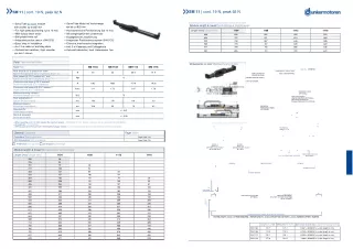
SM 11 | cont. 19 N, peak 92 N Module length & travel/Modullänge & Verfahrwege Length (mm)/Länge (mm) 868 894 920 945 971 997 »»ServoTube Modul mit Verfahrwege von bis zu 825 mm »»Hochdynamische Positionierung (bis 10 m/s) »»Mit stangengeführtem Linearmotor »»Kugelgeführte Linearführung »»Integriertes Positionsmesssystem (SIN/COS) »»Einfache, mechanische Integration »»Inkl. 3 m Kabelsatz und Schleppkette »»Optional Endschalter | hoch. Gebersystem 1μm SM 11 | cont. 19 N, peak 92 N »»ServoTube dc motor module with strokesup to 825 mm »»For high speed positioning (up to 10 m/s) »»With tubular linear motor »»Ball guided linear rail »»Integrated postion sensor (SIN/COS) »»Easy “drop in” installation »»Incl. 3 m cable set and drag chain »»Optional limit switches | high. encoder sys-tem 1 micron 1104 1108 1112 1116 696 722 748 773 799 645 671 697 722 748 593 619 645 670 696 543 569 595 620 646 825 774 722 672 Data/Technische Daten Dimensions in mm/Maßzeichnung in mm SM 1108 Type/Typ SM 1104 SM 1112 SM 1116 Doc. No. DR00104 Peak force @ 25°C ambient for 1 sec/ Spitzen-Schubkraft @ 25°C Umgebung, Dauer: 1s Peak current @ 25°C ambient for 1 sec/ Spitzenstrom @ 25°C Umgebung, Dauer: 1s Continuous stall force @ 25°C ambient/ Dauer-Schubkraft @ 25°C Umgebung Continuous stall current @ 25°C ambient*/ Dauer-Strom @ 25°C Umgebung* Maximum working voltage(1)/ Maximale Betriebsspannung(1) Peak acceleration(2)/ Spitzen-Beschleunigung(2) Maximum speed(3)/ Maximalgeschwindigkeit(3) Repeatability/ Wiederholgenauigkeit Absolute accuracy/ Absolutgenauigkeit 11 MAGNETIC THRUST ROD N 46 53 68.9 91.9 ) DRAG CHAIN FOR CABLE ROUTING (NOT LOAD BEARING) ) Apk 12 (LARGER SIZE OPTIONAL) ) ) STB11xx FORCER N 6.02 10.83 15.18 19.28 STANDARD THRUST ROD SUPPORT (ADJUSTABLE THRUST ROD SUPPORT OVER 508mm SYSTEM LENGTH) SHW LM BEARING RAIL Arms 1.11 1.73 1.87 1.78 ENCODER STRIP (OPTIONAL) VDC 75 RENISHAW RGH24 LINEAR ENCODER (OPTIONAL) [DATUM ACTUATION AT 20.0mm FROM END OF STROKE] 2 m/s 156 119 110 121 m/s 10.8 9.5 7.9 8.2 ENCODER REFERENCE MARK (OPTIONAL) SYSTEM CLAMPS (MOUNTED NOT LESS THAN 100mm APART) EACH SIDE, IF REQUIRED mm +/- 0.01 109 71 mm +/- 0.35 40 (1) When operating at 24 V or 48 V reduces the maximum speed./(1)Bei Betrieb mit 24 V oder 48 V reduziert sich die maximale Geschwindigkeit. (2) No playload./(2)Ohne Nutzlast. (3) Without payload to the maximum stroke length (triangular motion)../(3)Ohne Nutzlast über die maximale Hublänge (Dreiecksbewegung). 43 SECTION A-A SCALE 1 : 1.25 1 4 28 5 3 10 6 Options/Optionen Controllers/Regelelektroniken SI10 Interpolator/SI10 Interpolator Page/Seite 58 2 3 56 1 Page/ Seite 178 6 Page/ Seite 148 Preference/Vorzugsreihe On request/auf Anfrage DETAIL B SCALE 2 : 1 DETAIL C SCALE 2 : 1 EXTRUDED SLOTS TO SUIT M4 SQUARE NUTS EXTRUDED SLOTS TO SUIT M4 T-NUTS Module length & travel/Modullänge & Verfahrwege Length (mm)/Länge (mm) 200 226 251 277 303 329 354 380 406 431 457 483 508 534 560 586 611 637 663 688 714 740 765 791 817 843 B C = 35 = 4656 60 1112 1104 1108 1116 (FOR LARGER DRAG CHAIN SEE OPTION 3) 70 ±0.5 (SYSTEM CLAMP CENTRES) 28 54 79 105 131 157 182 208 234 259 - - - - - - - - - - - - (STROKE) FORCER LENGTH (STROKE) 28 54 80 106 131 157 183 208 A 2 (RUBBER BUFFER) 2 (RUBBER BUMPER) 28 54 79 105 131 156 29 55 81 106 2.5 EACH END A 285 311 336 362 388 414 439 465 491 516 542 568 593 619 645 671 234 260 285 311 337 363 388 414 440 465 491 517 542 568 594 620 182 208 233 259 285 311 336 362 388 413 439 465 490 516 542 568 132 158 183 209 235 261 286 312 338 363 389 415 440 466 492 518 22 22 CUSTOMER ADJUSTABLE LIMIT LIMIT SWITCH ACTUATOR SWITCHES (OPTIONAL) [FACTORY SET FOR 5.0mm FROM END OF STROKE] (OPTIONAL) 64(ADJUSTABLEROD SUPPORT) 7151 STANDARD SYSTEM LENGTH (200mm MIN TO 997mm MAX) SYSTEM LENGTH ( 0.5mm) = STROKE REQUIRED + FORCER LENGTH + 44.0mm (THRUST ROD SUPPORTS) + 4.0mm (RUBBER BUFFERS / BUMPER) Length/Längemm With buffers/Mit Puffer Approximate module mass/Ungefähres Modulgewichtkg 123.7 127.7 174.9 178.9 226,1 230.1 277,0 281.0 SM 1104 0.661 + (0.003251 x system length in mm) SM 1108 0.758 + (0.003251 x system length in mm) SM 1112 0.958 + (0.003251 x system length in mm) SM 1116 1.086 + (0.003251 x system length in mm)
150 | we also manufacture bldc motor and Venetian blinds for more detailsVisit www.dunkermotoren.com for further product information/ Besuchen Sie www.dunkermotoren.de für weitere Produktinformationen Visit www.dunkermotoren.com for further product information/Besuchen Sie www.dunkermotoren.de für weitere Produktinformationen| 151 https://sites.google.com/view/sm11cont19npeak92n/home