Download
1 / 55
550 likes | 592 Views
Learn about the development and implementation of the NICMOS Cooling System for Hubble Space Telescope, addressing thermal short issues, preserving imaging capabilities, and extending mission lifespan.

E N D
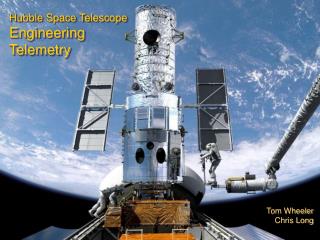
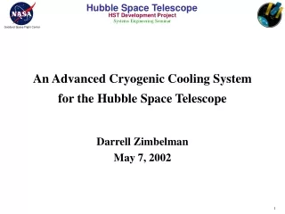
An Advanced Cryogenic Cooling System for the Hubble Space Telescope Darrell Zimbelman May 7, 2002
Agenda • NICMOS Instrument • The Problem • Solution(s) • NCS Overview • Results • Summary
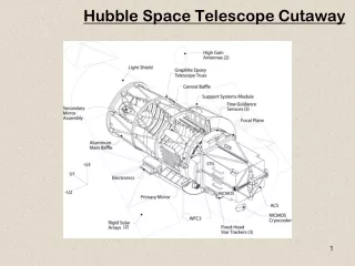
Near Infrared Camera and Multi-Object Spectrometer (NICMOS) Instrument • Instrument installed into HST during Servicing Mission 2 in February 1997 • NICMOS is the only Infrared (IR) imaging capability on HST • Designed to take images and low/moderate resolution spectra (/ 200) with high angular resolution (0.1 - 0.4 arc-second) at near-IR wavelengths ( = 0.8 to 2.5 µm) • Three cameras designed for simultaneous operations • Each camera contains a dedicated 256 x 256 Pixel HgCdTe detector • Detectors are mounted to the cold optics bench housed in a hybrid dewar (solid nitrogen within aluminum foam) that maintains their temperature at 58 K with a stability of +/- 2 K • Designed for a 5 year mission lifetime
The Problem • A thermal short between the cold baffles and the surrounding Vapor Cooled Shield (VCS) became apparent shortly after installation • Moved the focus of Camera 3 outside the adjustment range which eliminated ability to simultaneously focus all three cameras • However camera 3 was still capable of limited science operations • Increased the parasitic heat loading (~422 mW) which in turn reduced lifetime of the cryogen and thus the anticipated period of science operations (60 months to 22 months) • Post launch investigation concluded that the thermal short was caused by over filling of the dewar followed by expansion of the cryogen during ground cooling operations
NICMOS Dewar Continued Thermal Short
Solution(s) Short Term • A “fast track” call for proposals and increased allocation of HST time to NICMOS science was instituted in May 1997 to maximize potential benefit • Scientific program concluded on November 15, 1998 • Cryogen depleted on January 4,1999 • Monitor and quantify detector warm up characteristics Long Term • Retrieve, repair, and return NICMOS to HST • Replace NICMOS with a new IR instrument • Revive NICMOS with a cryogenic cooling system
Constructive Intervention • Develop a cryogenic system, the NICMOS Cooling System (NCS), to restore NICMOS scientific performance and extend life of the instrument beyond original plans • Motivation • NICMOS is a critical trailblazer for future IR missions, direct predecessor of NGST • Ideal instrument for observing relatively cool objects (brown dwarf stars and proto-planets) • Possesses ability to peer into molecular clouds and other regions obscured by interstellar dust (star and planet forming regions) • Retains several advantages over ground based telescopes with adaptive optics: • Much lower level of background light - allows higher sensitivity in H and J bands • More accurate photometry - allows for more more precise quantitative measurements • Greater sky coverage and point spread function
Key System Requirements • Remove 7 W including parasitic heat loads from the NICMOS instrument • Achieve detector temperatures of < 75 K where effective imaging can occur (balance between quantum efficiency and dark current count) • Thermal stability of 0.1 K/orbit (short term) and 0.5 K/year (long term) for detector calibration • Dissipate 450 W of power • Jitter allocation of 0.89 mas rms (0.77 mas for cooler and 0.45 mas for radiator) of the overall HST jitter performance requirement of 7 mas rms • Interface to existing HST electrical and mechanical systems
Challenges • Develop, test and install a new system that was never intended to be used on HST • No pre-defined interfaces (mechanical or electrical) • EVA compatible • A critical element of the system (i.e. NICMOS) was on-orbit • Condition of the on-orbit element • Interface issues • Not able to characterize end-to-end system performance • Adhere to a strict “Do No Harm” policy • No added risk to HST • No degradation to the pre-installation HST performance • Minimize cost and accelerate schedule
Key Trades • Cryo Cooler Technology • Existing systems versus a new technology development effort • Jitter requirement excluded existing systems • New technology effort was selected based on initial assessments of the jitter performance and the ability to satisfy the derived temperature level/stability requirements • Moisture mitigation strategy • Heat Removal System • Heat Pipes versus a Capillary Pumped Loop (CPL) versus a Loop Heat Pipe (LHP) • LHP and heat pipe designs were incompatible with installation • CPL provided installation flexibility and autonomous control capability • EVA Time • Efficiency versus design versus cost • Maximize time efficiency with simplified designs
Technology Readiness Cryo Cooler • Cooler technology was at a TRL 2/3 when the development began • Matured the cooler technology from a TRL 2/3 to a TRL 7 in 18 months • Flight demonstration during October 1998 (STS-95) • Completed maturation to TRL 9 by February 2002 • Fully operational system for HST Servicing Mission 3B All other elements were at high TRLs
NCS Overview • NCS is comprised of three major elements: Electronics Support Module (ESM), NICMOS Cryo Cooler (NCC), CPL/Radiator Assembly • ESM provides the command, control and telemetry functions • NCC cools the NICMOS detectors by circulating Neon through the existing plumbing • Plumbing was originally used to circulate Helium to freeze the liquid nitrogen in the dewar • EVA friendly bayonet interface between NCC and NICMOS • Removes reliance on expendable cryogens • CPL/Radiator Assembly transfers heat from the NCC to the external environment • High heat transport capability • Capacity is in excess of that required for the NCC under any operating condition • Excess capacity can be utilized for future needs via an interface plate on the radiator • Associated mechanisms and harnessing to connect elements • Cryo Vent Insert • Ground Strap Adapter • COSTAR Y Harness • Cross Aft Shroud Harness (CASH) • P600 Harness
NCS Installation (-V2) ESM COSTAR Y Harness
NCS Installation (+V2) Neon Flex Lines NCC CPL Line Cryo Vent Insert
NCS Installation (-V3) NCS Radiator NCS Conduit
NCS Internal Layout Cryo Vent Insert COSTAR Y Harness CPL NCC ESM CASH NCS Radiator
ESM • Provides the monitoring and control functions for the NCS • Interfaces with the NCS hardware and HST • Controls the NCC (i.e. the NICMOS detector temperatures) and keeps the turbo-machines within their operating limits • Proportional Integral Derivative control law is used to set the compressor speed, within limits of compressor housing temperature and turbo-alternator speed, to zero the temperature error between the desired NICMOS temperature and a defined set-point • Slip control law for efficient compressor operation • Monitors the CPL and adjusts the heater set-points to provide a stable temperature at the Heat Rejection Interface (HRI) while protecting the loop from deprime
ESM Continued • HST Electrical Interfaces • Power interface • COSTAR Y harness from COSTAR PDU • Data interface from HST SI C&DH to redundant RIUs • COSTAR Y harness from COSTAR • ESM Electrical Interfaces • Aft Shroud Cooling System (ASCS) harness from the ASCS radiator • COSTARY Y harness from COSTAR • CASH from the NCC • HST Mechanical Interfaces • 2 EVA operated latches mounted to the ESM bridge-plate provide interface to aft shroud • Bridge Latch 1 is an EVA actuated rack and pinion plunger design that engages the support standoffs of the center guide rail • Bridge Latch 2 is an EVA actuated ratchet and pawl mechanism that clamps onto the SI connector handhold
Bridge Latches Bridge Latch 1 Bridge Latch 2
NCC • Employs two separate cooling loops: Circulator and Cryocooler • Circulator Loop uses a centrifugal circulator to pump a constant flow of neon between the NCC and NICMOS • EVA installed titanium bayonet fittings attach to the Coolant In and Coolant Out female bayonet interfaces on the NICMOS Cryo Interface • Uses neon at a 4 atm design pressure and a nominal operating speed of 1200 rps to provide a flow rate of 0.4 g/s • Removes heat from the NICMOS instrument and conductive parasitics • Heat is transferred from the Circulator Loop to the Cryocooler Loop via the Cold Load Interface • Stainless Steel counter-flow fin-type heat exchanger with a thermal effectiveness is 0.963 • Provides structural support for the circulator, turbo-alternator, and recuperator
NCC Continued • Cryocooler Loop uses two high-speed turbo-machines to provide compression and expansion of the neon and transfers heat to the HRI • HRI provides a conductive coupling between the NCC and the CPL • Turbo-alternator provides the refrigeration at the cold end of the loop • Work is extracted by expansion of gas across the turbine rotor • Shaft work is then converted to electrical power by the alternator and conveyed to a selectable resistive load where it is dissipated as heat and rejected to the HRI • Compressor provides compression at the warm end of the loop • Centrifugal machine driven by a 3-phase induction motor with a maximum operating speed of 7500 rps • Includes an integral fin-type after-cooler • Bolted to the HRI
NCC Continued • Recuperator provides heat transfer between the high and low pressure streams of gas in the cryocooler loop • Consists of 300 slotted copper disks equally spaced in a stainless steel outer shell • Flow is separated by stainless steel spacer rings between adjacent pairs of disks • Supported by the CLI on the cold end and the NCC structure on the warm end
NCC Continued • Thermal Interface • Copper saddle provides a conductive joint between HRI and CPL evaporator • Evaporator is installed via EVA operations • Pressure required to meet conduction requirement is achieved by EVA installation of a cover plate that bolts to the copper saddle • Cryo Valve Heaters • Provide heat to the NICMOS cryo valve inlet/outlet valve handles to keep the viton o-rings above their leak temperature threshold under all HST environments • EVA installed over NICMOS cryo valve handles
NCC Continued • NCC Electrical Interfaces • Harness from the radiator • CASH from the ESM • HST Mechanical Interfaces • 2 EVA operated wing-tab bayonet fittings attached to the NICMOS cryo interface plate • 2 EVA operated snap-on valve heater assemblies attached to the NICMOS cryo valve handles • 2 EVA operated latches identical to ESM
NEON LINE FROM NICMOS NEON LINE TO NICMOS CIRCULATOR FILTER TURBOALTERNATOR COLD LOAD INTERFACE CIRCULATOR CIRCULATOR REFILL TANK RECUPERATOR POWER CONVERSION ELECTRONICS ACCUMULATOR TANK (1 of 2) COMPRESSOR/ AFTERCOOLER PRESSURE TRANSDUCER CIRCULATOR MAIN TANK COMPRESSOR FILTER NCC Continued
NICMOS Interface Panel Coolant IN Bayonet Port Coolant IN Cryo Valve Coolant OUT Bayonet Port Coolant OUT Cryo Valve
CPL/Radiator Assembly • CPL/Radiator Assembly interfaces to the NCC at the HRI via the CPL evaporator which carries heat from the NCC to the external radiator • Cold liquid coming from the radiator flows into the evaporator and is vaporized transferring heat from the NCC • Hot vapor carries heat out of the evaporator to the radiator via stainless steel tubing • Vapor enters a heat pipe heat exchanger in the radiator and condenses in header heat pipe • Heat from the header heat pipe is conducted to a series of spreader heat pipes throughout the radiator where heat is then radiated to the space environment • Condensed vapor moves through a subcooler region to cool the liquid prior to exiting the radiator
CPL/Radiator Assembly Continued • HST Electrical Interfaces • P600 Harness • Power from the HST EPS Test Plug to Radiator Diode Box • CPL/Radiator Electrical Interfaces • Radiator harness to NCC • HST Mechanical Interfaces • Mounts to exterior of aft shroud • Attached to HST handrails with 3 EVA actuated over-the-center latches • Latches are attached to radiator with titanium flexures • Flex lines from the evaporators feed through the aft shroud cryo vent where they transition to rigid lines running through the conduit which traverses the aft bulkhead • Cryo Vent Insert provides the sole mechanical connection of conduit to aft bulkhead • The rigid lines transition back to flex lines upon exiting the conduit and back to rigid lines at the radiator strain relief bracket
Condenser P T Reservoir Evaporator CPL/Radiator Assembly Continued Q Radiator Q Heater Q NCC
CPL/Radiator Assembly Continued Subcooler Section Isothermalizer heat pipes Heat Pipe Heat Exchangers Reservoir Lines
Vapor Transport Lines Heat Pipe Heat Exchangers Liquid Return Subcooler Reservoir Lines 4-13 CPL/Radiator Assembly Continued
Cryo Vent Insert Pawl Levers Lock Down Ring Stove Pipe (Attached to conduit)
HST Orbital Systems Test • Flight demonstration to provide system validation and enhanced system knowledge beyond what could be accomplished through ground testing (STS 95, October 1998) • Resulted in 185 hours of anomaly free operation • A minimum temperature of 72.65 K and stability of 0.1 K was reached using a surrogate representation of the NICMOS dewar called the NICMOS Cooling Loop Simulator (NCLS) • Vibration measurements were obtained during various operational and non-operational periods to characterize vibration signatures • Results concluded that disturbances below 2 Hz produce the majority of contribution to HST jitter, while data resolution and corruption identified the need for further ground testing to reduce uncertainties attributed to mass participation and systematic errors
Specialized Testing • NCS was held to more stringent EMI/EMC test levels to minimize/eliminate risk to the telescope • NICMOS spare detector noise test • Prove that there was no conducted noise into the NICMOS instrument via the NCC • Vibration Emittance Test • Suspended NCC in micro-g environment to characterize the vibration behavior • Test results showed that NCC induced vibrations were within acceptable HST limits • Radiator RF Emission Test • Developed a grounding plate for the radiator at the telescope entrance • No significant change with or without grounding plate • Thermal Glove Box Testing • Evaluate all EVA interfaces at temperature extremes • High Fidelity Mechanical Simulator/Vehicle Electrical System Test • Crew Training